Device and method for controlling machine tool

a technology of machine tools and control axes, which is applied in the direction of electric programme control, program control, instruments, etc., can solve the problems of deterioration of the processing accuracy of workpieces, increased equipment costs of machine tools, and difficulty in ensuring installation space or maintaining reliability of position detectors, so as to achieve stable and accurate motion control of control axes, quick and appropriate elimination of interference, and improved workpiece processing accuracy

Active Publication Date: 2010-12-07
FANUC LTD
View PDF12 Cites 8 Cited by
  • Summary
  • Abstract
  • Description
  • Claims
  • Application Information

AI Technical Summary

Benefits of technology

[0011]It is an object of the present invention to provide a device for controlling a feed control axis and a rotary control axis, both provided in a machine tool in which the rotary control axis is fed along the feed control axis, wherein it is possible to quickly and appropriately eliminate interference between the feed control axis and the rotary control axis so as to implement stable and accurate motion control of the control axes, and thereby to improve a processing accuracy of a workpiece.
[0012]It is another object of the present invention to provide a method for controlling a feed control axis and a rotary control axis, both provided in a machine tool in which the rotary control axis is fed along the feed control axis, wherein it is possible to quickly and appropriately eliminate interference between the feed control axis and the rotary control axis so as to implement stable and accurate motion control of the control axes, and thereby to improve a processing accuracy of a workpiece.

Problems solved by technology

In the above machine tool, the feed control axis and the rotary control axis may exert a mechanical or dynamic effect (i.e., an interference) resulted from their respective motions on each other, which may affect the stability of position control of each axis and thus may result in the deterioration of the processing accuracy of a workpiece.
However, in the case where such a position detector is installed in a machine tool, equipment costs of the machine tool may increase, and since the machine tool is often placed in poor environments, problems in ensuring installation space or maintaining reliability of the position detector may arise.
Moreover, it is difficult to adapt a technique for correcting the command value given to the stator, on the basis of the actual value of the displacement of the stator, to a quick and accurate positioning control for a movable section in a typical machine tool.
Such a configuration may be effective for controlling a robot, in which the moving speed or positional accuracy of an arm is lower than that of the movable section in the typical machine tools, but may also be difficult to be adapted to the control of the machine tool requiring the quick and accurate positioning.

Method used


Image

  • Device and method for controlling machine tool
  • Device and method for controlling machine tool
  • Device and method for controlling machine tool

Examples


Embodiment Construction

[0031]The embodiments of the present invention are described below, in detail, with reference to the accompanying drawings. In the drawings, the same or similar components are denoted by common reference numerals.

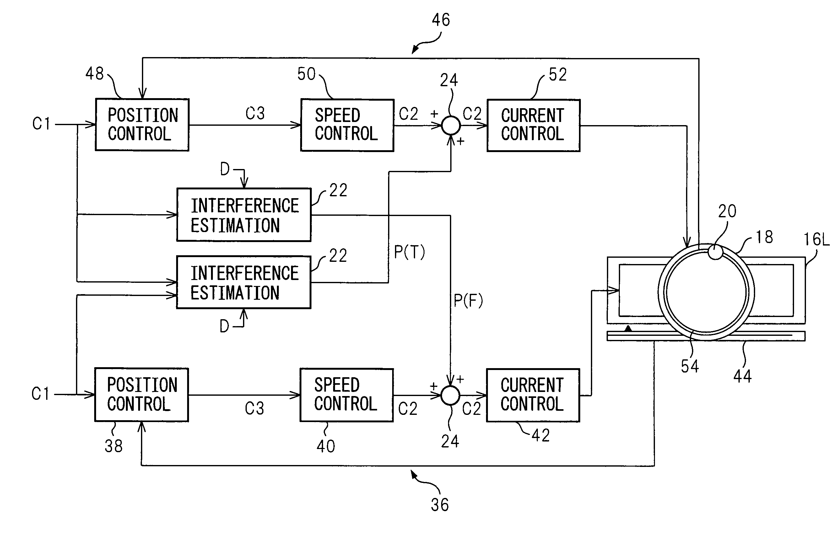
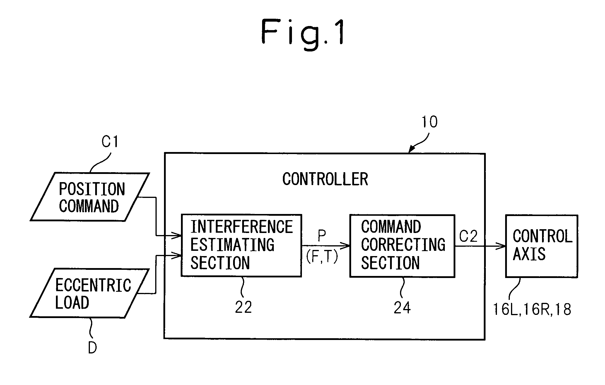
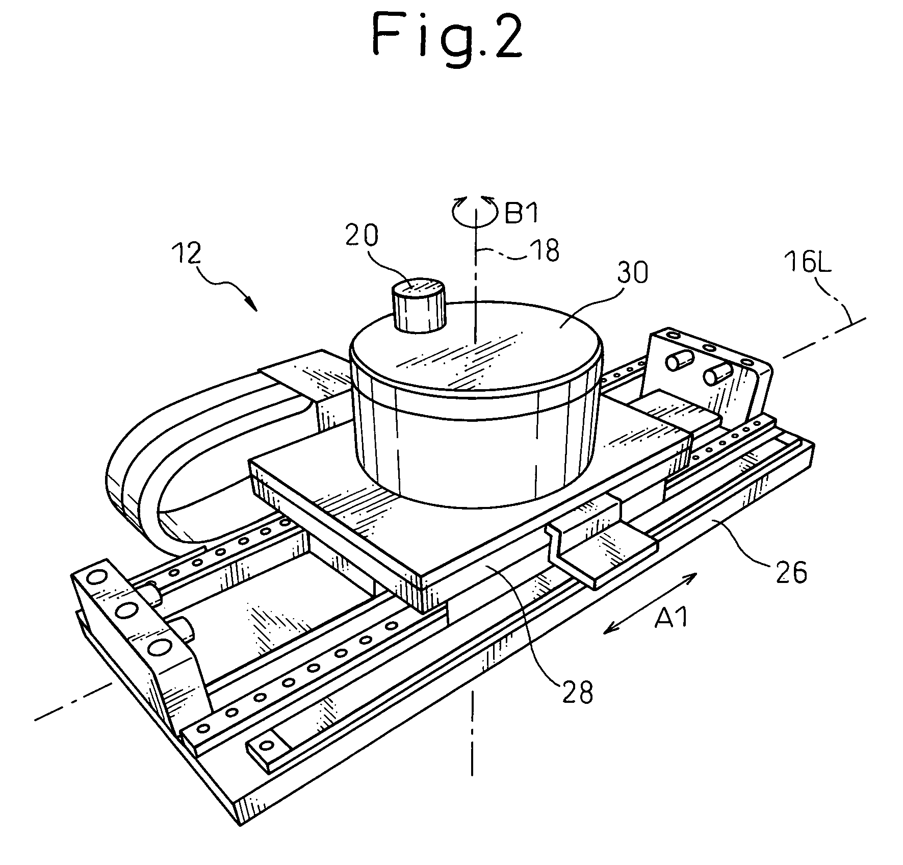
[0032]Referring to the drawings, FIG. 1 shows, by a functional block diagram, a basic configuration of a controller (or a control device) 10 of an electric motor, according to the present invention. FIGS. 2 and 3 illustrate major parts of two representative examples of machine tools 12 and 14, respectively, to which the controller 10 can be applied. The machine tool 12, 14 is provided with a feed control axis 16L, 16R that performs a linear or rotational feed motion, and a rotary control axis 18 that is arranged on the feed control axis 16L, 16R so as to be fed along the feed control axes 16L, 16R and to perform a rotary indexing motion. The controller 10 has a configuration for controlling a feed motion of the feed control axis 16L, 16R and a rotary motion of the rotary co...


PUM


Abstract

A device for controlling a feed motion of a feed control axis and a rotary motion of a rotary control axis, both axes being provided in a machine tool so that the rotary control axis is fed along the feed control axis. The device includes an interference estimating section estimating an interference generated between the feed control axis and the rotary control axis, based on a position command instructed to at least one of the feed control axis and the rotary control axis and a position and mass information of an eccentric load carried by the rotary control axis; and a command correcting section correcting a current command given to at least one of the feed control axis and the rotary control axis, based on the interference estimated by the interference estimating section.

Description

BACKGROUND OF THE INVENTION[0001]1. Field of the Invention[0002]The present invention relates to control of a machine tool, and more particularly to device and method for controlling a feed control axis and a rotary control axis, both provided in a machine tool in which the rotary control axis is fed along the feed control axis.[0003]2. Description of the Related Art[0004]A machine tool provided with a feed control axis performing a linear or rotational feed motion and a rotary control axis adapted to be fed along the feed control axis and performing a rotary indexing motion has been known. The feed control axis carries a structural member such as a linear slide or a rotational slide, and the rotary control axis carries a structural member such as a rotary indexing table or a turret tool rest.[0005]In the above machine tool, the feed control axis and the rotary control axis may exert a mechanical or dynamic effect (i.e., an interference) resulted from their respective motions on eac...

Claims


Application Information

Patent Timeline
Patent Type & Authority Patents(United States)
IPC IPC(8): G05B19/10
CPCG05B19/404G05B2219/49177G05B2219/49313G05B2219/50174
Inventor IWASHITA, YASUSUKEOKITA, TADASHIKAWAMURA, HIROYUKIMA, CHENGBIN
Owner FANUC LTD
Why Eureka
Try Eureka