Precision frequency change detector

a detector and frequency change technology, applied in the field of oscillators, can solve the problems of large user range error, unintended fractional frequency jump, and frequency jump, and achieve the effect of reducing the number of user range errors, reducing the range error, and reducing the accuracy of the detector

Inactive Publication Date: 2010-12-07
THE AEROSPACE CORPORATION
View PDF6 Cites 13 Cited by
  • Summary
  • Abstract
  • Description
  • Claims
  • Application Information

AI Technical Summary

Problems solved by technology

Although atomic frequency standards are well known for their frequency precision and stability, atomic frequency standards are also known to exhibit slight, but nonetheless significant, frequency jumps, caused by either environmental and external or internal clock physics perturbations.
In the GPS system, an unintended fractional frequency jump could produce a large user range error after just a few seconds.
However, for a moderate sized frequency jump, the user range error could build up to an unacceptably high level in less than a day, negatively affecting some precision navigation applications.
Frequency jump detection is a difficult problem, without a viable solution.

Method used


Image

  • Precision frequency change detector
  • Precision frequency change detector

Examples


Embodiment Construction

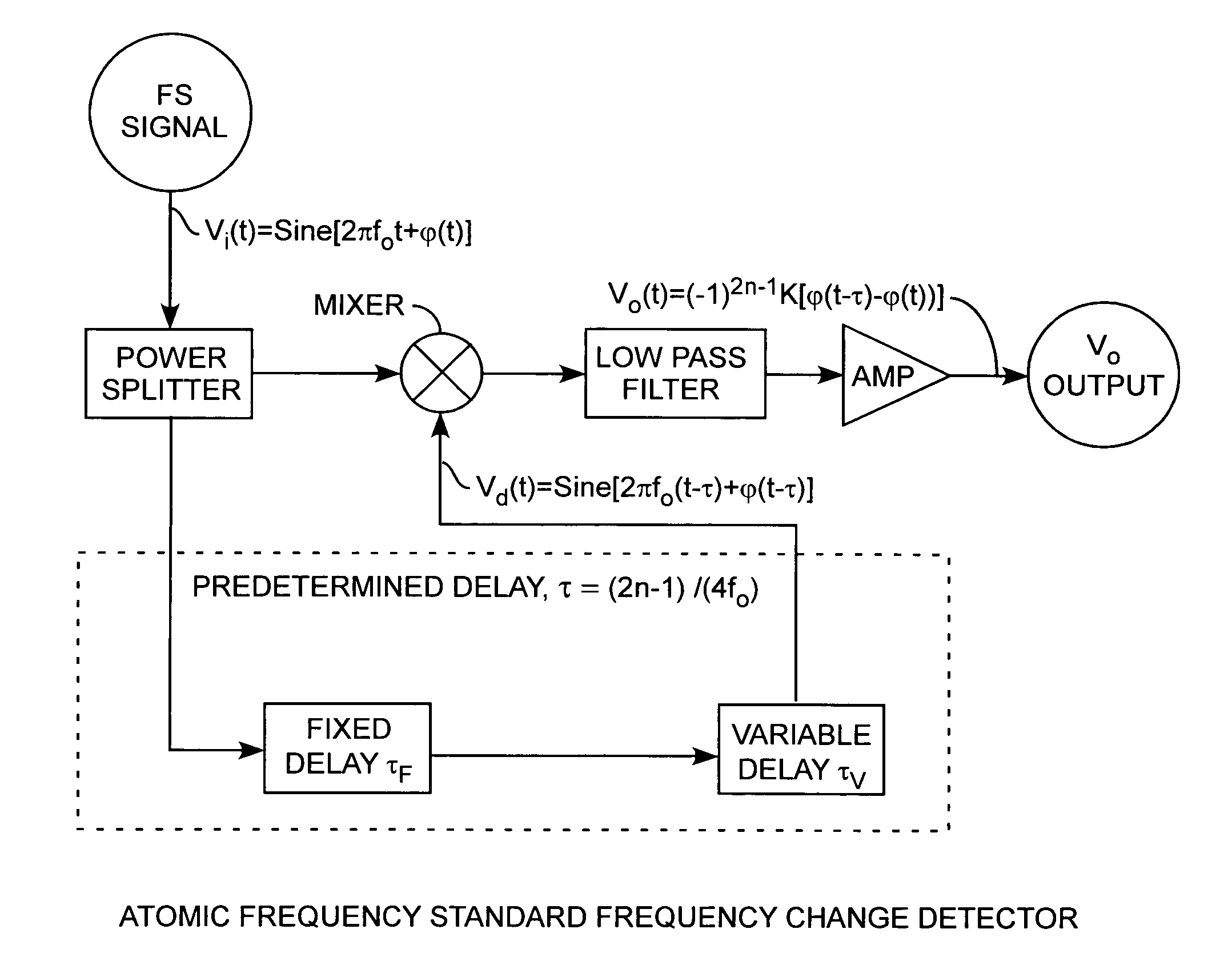
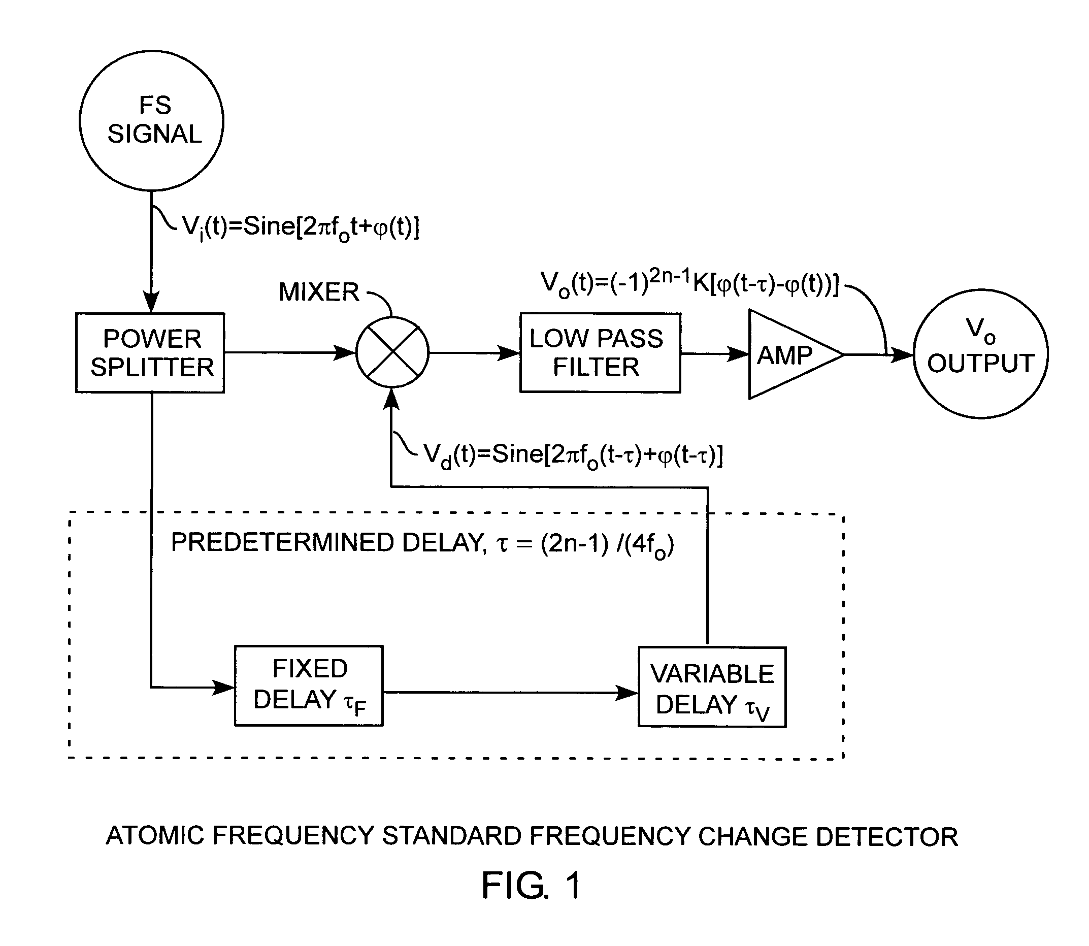
[0013]An embodiment of the invention is described with reference to the figure using reference designations as shown in the figure. Referring to the Figure, a frequency standard signal Vi(t)=sine[2πfot+φ(t)] is connected to a power splitter providing two identical undelayed frequency signals Vu of lower power than the frequency standard signal input Vi, where t is time, where fo is the center frequency of the frequency standard signal, and where φ(t) is the phase at time t. Both undelayed frequency signals Vu from the power splitter have the same frequency as the input frequency standard signal Vi(t).

[0014]A first one of the undelayed frequency signals Vu is fed into a predetermined delay τ, which is equal to (2n−1) / (4fo), where n is an integer. The predetermined delay preferably includes a fixed delay τF and a variable delay τv. The predetermined delay provides for a predetermined phase shift. Hence, the predetermined delay is matched to the center frequency fo of the frequency sta...


PUM


Abstract

A frequency change detector splits a frequency standard signal into two undelayed frequency signals, one of which is delayed by a predetermined amount. The delayed signal is then mixed with the undelayed frequency signal into a mixed signal that is further filtered and amplified for providing an output signal indicating frequency changes of the frequency standard signal. The mixed frequency signal indicates frequency changes of the original frequency standard signal without reference to another frequency standard. This frequency change detector is well suited for use on satellites as an early warning detection of changes in on-board atomic frequency standards.

Description

STATEMENT OF GOVERNMENT INTEREST[0001]The invention was made with Government support under contract No. FA8802-04-C-0001 by the Department of the Air Force. The Government has certain rights in the invention.FIELD OF THE INVENTION[0002]The invention relates to the field of oscillators. More particularly, the present invention relates to a detector for detecting frequency changes.BACKGROUND OF THE INVENTION[0003]Atomic frequency standards and high performance crystal oscillators are used in navigation and communication satellite systems. For example, GPS satellites use rubidium (Rb) atomic frequency standards or cesium (Cs) atomic frequency standards to generate signals in space with a very precise frequency for GPS users. Although atomic frequency standards are well known for their frequency precision and stability, atomic frequency standards are also known to exhibit slight, but nonetheless significant, frequency jumps, caused by either environmental and external or internal clock ...

Claims


Application Information

Patent Timeline
Patent Type & Authority Patents(United States)
IPC IPC(8): G01R23/02H03D3/00H03K9/06
CPCG01R25/00G01R29/26G01R23/00G01R23/14
Inventor CHAN, YAT C.CAMPARO, JAMES C.JOHNSON, WALTER A.HUMPHRIES, LEGAL REPRESENTATIVE, CHRISTINEYOUNG, ALBERT M.KARUZA, SARUNAS K.
Owner THE AEROSPACE CORPORATION
Why Eureka
Try Eureka