Method of driving liquid crystal display element

a technology of liquid crystal display element and display element, which is applied in the direction of instruments, static indicating devices, etc., to achieve the effects of preventing increases in driving voltage, excellent uniformity, and low voltage enduran

Inactive Publication Date: 2010-12-07
FUJITSU LTD
View PDF16 Cites 1 Cited by
  • Summary
  • Abstract
  • Description
  • Claims
  • Application Information

AI Technical Summary

Benefits of technology

[0043]It is an object of the present invention to provide a method of driving a liquid crystal display element, the method using an inexpensive and general purpose driver having a low voltage endurance, and the method being for realizing a multilevel halftone display that presents an excellent uniformity. In order to achieve this object, driving voltages and pulse widths are set to be variable for each step by applying, a plurality of times, pulses that are based on the cumulative response (overwriting) of liquid crystals, and the liquid crystals are controlled to be in a prescribed halftone state from the initial state of the reflection state by using a zone having a great margin. As a result of this, it is possible to prevent increases in the driving voltage, and accordingly a cheap general purpose driver that outputs binary values and that has a low voltage endurance can be used. Also, because a zone having a great margin is used for the halftone level conversion, a display with a multilevel halftone is realized while presenting an excellent uniformity even in an element with a low cell gap accuracy. Also, according to the present invention, it is possible to suppress increases in the number of overwriting times required even when the number of halftone levels increases.

Problems solved by technology

However, while this dynamic drive realizes quick operation, it causes large graininess in halftones.
Also, generally, this dynamic drive requires a dedicated driver that can output voltages at several levels, and the cost increases because of the production of the driver and complexity of the control circuit.
However, the problem of graininess is not solved by this dynamic drive.
However, in this method, the probability of large graininess in halftones still remains, and also it is difficult to implement this method at a low cost because the driving voltage is high, which is problematic.
The above driving methods are methods in which the initial state does not matter and the halftone zone B is used; accordingly, even though it allows for quick operation, the graininess is large and the display quality is low, which is problematic.
Also, Non Patent Document 2 discloses another driving method that uses the halftone zone A. However, this method also has a problem.
However, in this method, the driving voltage can be as high as 50-70V because of the high quasi moving-picture rate, which causes a higher cost, and also causes a lower display quality because the “Two phase cumulative drive scheme” described in Non Patent document 2 uses the cumulative response in two directions, i.e., the cumulative response to the planar state and the cumulative response to the focal conic state (in other words, to the halftone zone A and the halftone zone B), by using the two stages “preparation phase” and “selection phase”.
As described above, a display with a multilevel halftone in electronic paper that uses the conventional cholesteric liquid crystals requires a driver IC that is specially designed to create driving waveforms at multiple levels, and the driving voltage can be as high as 40-60V, thus requiring the IC to have a high voltage endurance, which has lead to a higher cost.
Also, the conventional techniques have a problem with graininess being large in halftones (low uniformity), and it is difficult to apply them to electronic paper that requires a high display quality.
This requires the construction of a driver IC or a peripheral circuit that can arbitrarily switch voltage values or the pulse widths, which has caused a higher cost.
Also, in this method, the driving margin of halftones is narrow, and graininess in halftones is large even when an element having a high uniformity in its cell gaps is used (for example with glass components), which has caused difficulty in realizing a high-quality display.Patent Document 1:Japanese Patent Application Publication No. 2001-228459Patent Document 2:Japanese Patent Application Publication No. 2003-228045Patent Document 3:Japanese Patent Application Publication No. 2000-2869Non Patent Document 1:A Novel Dynamic Drive Scheme for Reflective Cholesteric Displays, SID 02 DIGEST, pp 546-549, 2002.

Method used


Image

  • Method of driving liquid crystal display element
  • Method of driving liquid crystal display element
  • Method of driving liquid crystal display element

Examples


first embodiment

[0068]First, by referring to FIG. 2, the present invention is explained with an example of a display with four halftone levels. Because the example uses a four-level halftone display, each pixel in the displaying region is driven to display at one of the levels of a halftone ranging from level 0 through level 3 as shown as the complete pattern in FIG. 2.

[0069]As shown in FIG. 2, first in step 1, each pixel is driven to be in the planar state or in the focal conic state. Only the pixels at level 0 are driven to be in the focal conic state. In step 1, as shown in FIG. 2, driving to the planar state, i.e., to the reflection state is performed at 32V as the ON level, and driving to the focal conic state, i.e., to the non-reflection state is performed at 24V as the OFF level. Next, in substep 1 in step 2, regions other than the regions that have to be at level 3 of a halftone are selected, and the ON pulse (24V) that causes the transition to the focal conic state is applied to the select...

second embodiment

[0074]Next, a second embodiment in which the number of driving times is reduced is explained by using a display example with eight halftone levels, which is shown in FIG. 3.

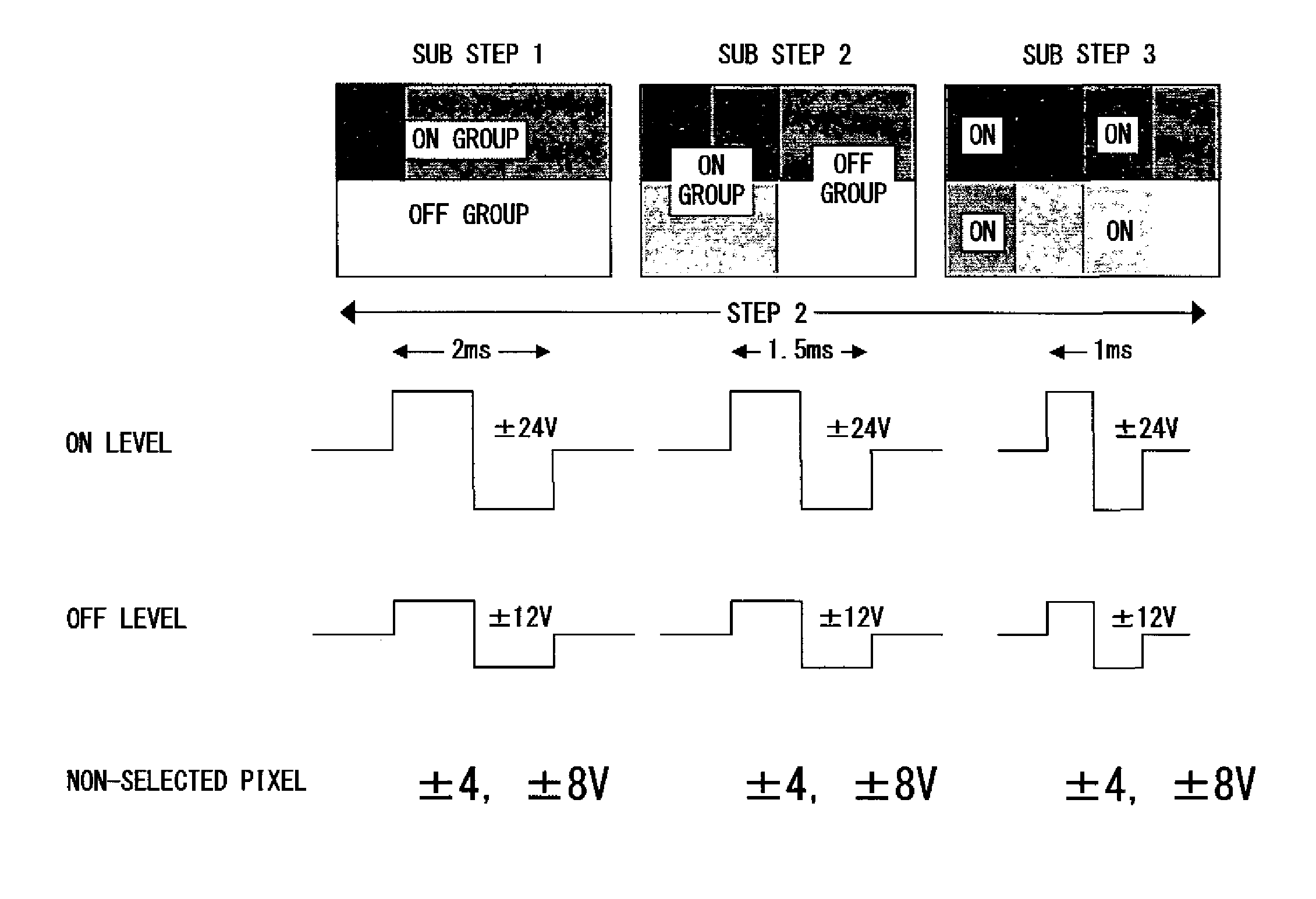
[0075]The operations performed until driving to the planar state and the focal conic state in step 1 are the same as those in the first embodiment. In step 2, in both the ON group that is to be driven and the OFF group that is not to be driven, the regions corresponding to halftone levels whose number is, for example, the half of the eight levels are selected, and the ON pulse is applied simultaneously to the selected regions as the ON group in substep 1 in step 2.

[0076]Next, a number of regions equal to half the number of the halftone levels are selected in both the ON group and the OFF group set in step 1, and the ON pulse is applied to the selected regions, which will be handled as the ON group in substep 2. This method is used in step 3; in other words, a number of regions equal to half the number of halftone...


PUM


Abstract

In order to realize a display with a multilevel halftone that is excellent in uniformity by using a liquid crystal display element employing an inexpensive and general purpose driver having a low voltage endurance, a pulse application employing a cumulative response (overwriting) of liquid crystals is performed a plurality of times, the driving voltage and the pulse width are set to be variable for each step, and the liquid crystals are controlled to be in a prescribed halftone state by using a region having a large margin from a reflection state as the initial state. Since an increase in drive voltage is prevented, an inexpensive binary output general purpose driver having a low voltage endurance can be used. Furthermore, a display with a multilevel halftone that is excellent in uniformity is realized because of a gray level conversion that uses a region having a large margin.

Description

CROSS REFERENCE TO RELATED APPLICATION[0001]This application is a continuation of international PCT application No. PCT / JP2005 / 005777 filed on Mar. 28, 2005.BACKGROUND OF THE INVENTION[0002]1. Field of the Invention[0003]The present invention relates to a method of driving a display element that uses cholesteric liquid crystals, and particularly to a method of driving a display element by which a high-quality display with a multilevel halftone is realized.[0004]2. Description of the Related Art[0005]In recent years, electronic paper has been vigorously developed by companies and universities. Electronic paper can be applied to various portable devices including electronic books, sub-displays in mobile terminals, and display units in IC cards.[0006]One effective way to realize electronic paper is to utilize cholesteric liquid crystals.[0007]A cholesteric liquid crystal has excellent characteristics, including an ability to hold a display state semi-permanently (image memory character...

Claims


Application Information

Patent Timeline
Patent Type & Authority Patents(United States)
IPC IPC(8): G09G3/36
CPCG09G3/2081G09G3/3629G09G3/2018G09G3/3607G09G2300/023G09G2300/0473G09G2300/0486G09G2310/06G09G2310/062G09G2310/065G09G2320/0209G09G2320/0238G09G2330/025
Inventor NOSE, MASAKI
Owner FUJITSU LTD
Why Eureka
Try Eureka