Viscous rotary damper for vehicle end gate assembly

a technology of end gate and rotary damper, which is applied in the direction of shock absorbers, roofs, transportation items, etc., can solve the problems of noise and object impact, and achieve the effect of slowing down the movement of the end gate and dissipating kinetic energy

Active Publication Date: 2010-12-14
GM GLOBAL TECH OPERATIONS LLC
View PDF50 Cites 17 Cited by
  • Summary
  • Abstract
  • Description
  • Claims
  • Application Information

AI Technical Summary

Benefits of technology

[0009]According to another aspect, the fluid chamber has an outer wall with a radius that varies with respect to the axis of rotation of the impeller member. Put another way, the eccentric clearance between the impeller member and side wall of the fluid chamber changes, creating different degrees of kinetic energy dissipation.
[0011]In accordance with yet another aspect, the first end of the impeller member is a trunnion post configured to be releasably received by a trunnion cup secured to or formed in the end gate assembly. In effect, the damping device replaces one of the prior art body-side trunnion post assemblies, but offers the damping characteristics described above while maintaining removability of the end gate assembly.
[0012]According to an additional aspect, each blade is connected to the mast such that the kinetic energy dissipation characteristics of the impeller member are greater when the end gate assembly transitions from the first position to the second position than when transitioning from the second position to the first position. Ideally, each blade is hinged (e.g., via a mechanical or a “live” hinge) to the second end of the mast. The hinged engagement allows the blade to extend radially outward from the mast when the end gate assembly transitions from the first position to the second position, but lies generally flush against the mast when the end gate assembly transitions from the second position to the first position.
[0013]According to another embodiment of the present invention, a damping device for an end gate assembly is presented. The end gate assembly is pivotably mounted to the rearward portion of a vehicle body to transition from a closed position to an open position. The damping device includes a housing member configured to positively attach to the vehicle body. The housing member defines a generally circular fluid chamber therein. The fluid chamber has first and second compartment halves each with viscous fluid therein. The damping device also includes an impeller member having a mast with first and second opposing ends. The first end is configured to mate with the end gate assembly. The second end has first and second blades projecting radially outward therefrom. The first and second blades are respectively rotatably received inside the first and second compartment halves whereby the impeller member dissipates kinetic energy generated by the end gate assembly when transitioning between the closed and open positions. The level of dissipation increases as the end gate assembly transitions from the closed position to the open position, but decreases as the end gate assembly transitions from the open position to the closed position.

Problems solved by technology

Although torque rod based tailgate counterbalancing hinge designs, such as those discussed above, reduce efforts in opening and closing the tailgate, the end gate can cause an objectionable impact and noise if allowed to free fall into the open position.

Method used


Image

  • Viscous rotary damper for vehicle end gate assembly
  • Viscous rotary damper for vehicle end gate assembly
  • Viscous rotary damper for vehicle end gate assembly

Examples


Embodiment Construction

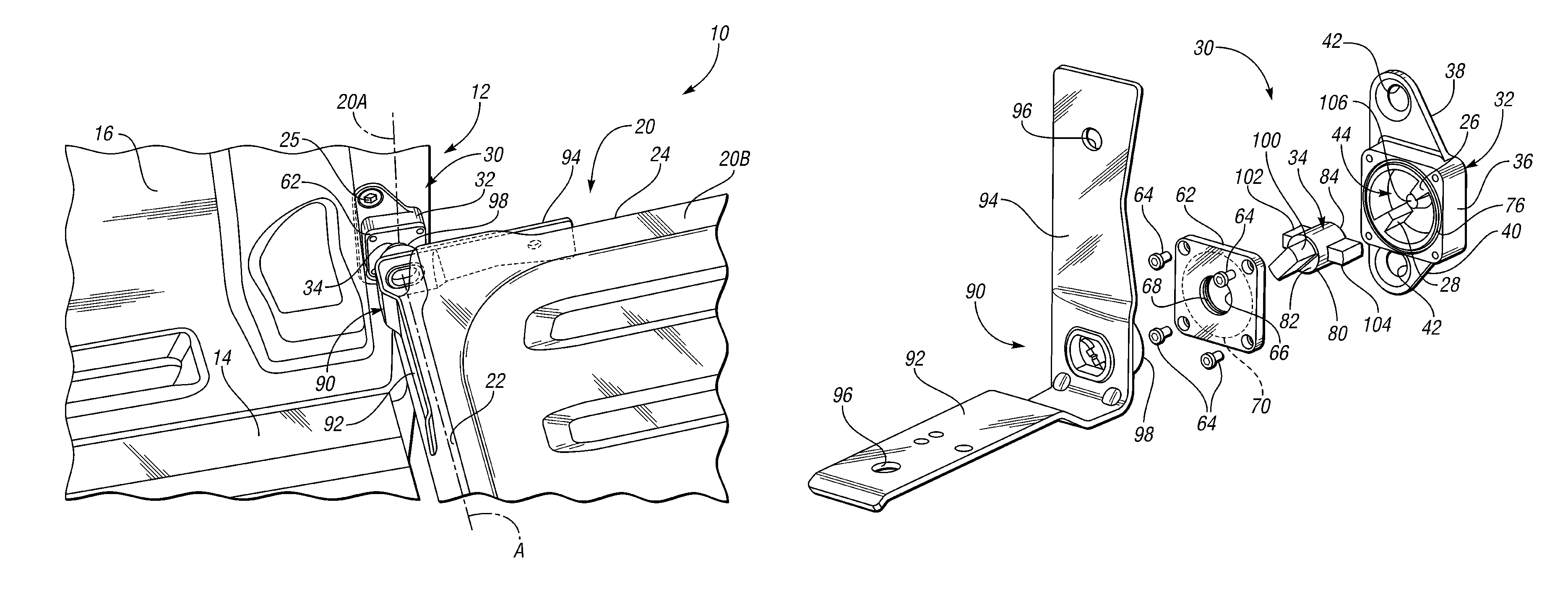
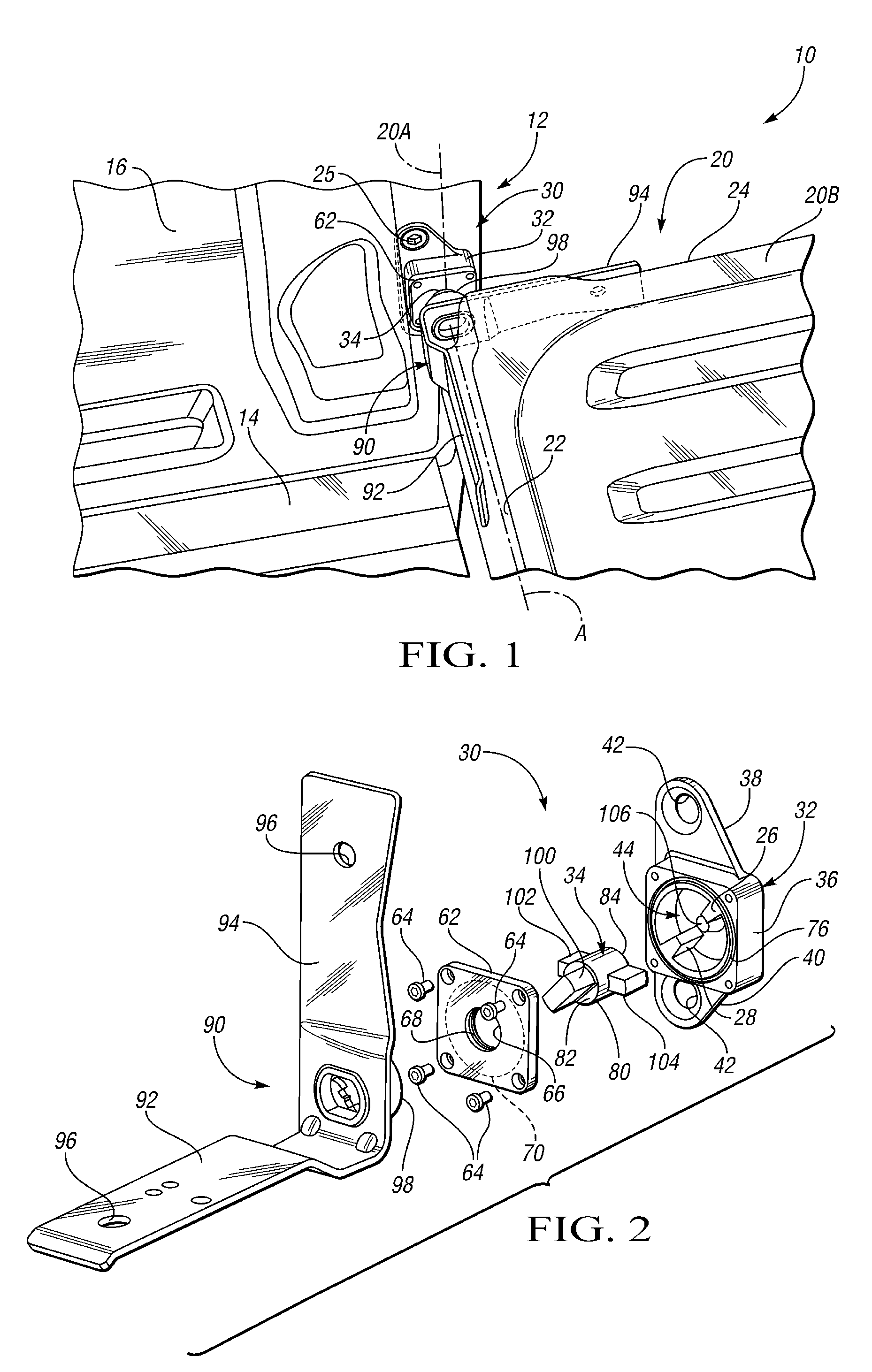
[0027]Referring to the drawings, wherein like reference numbers refer to like components throughout the several views, FIG. 1 illustrates a representative motorized vehicle, indicated generally at 10, with which the present invention may be incorporated and practiced. The present invention is described herein in the context of a standard pickup truck of conventional construction, offering a representative application by which the present invention may be utilized. However, the present invention is in no way limited to the particular vehicle configuration illustrated in FIG. 1. In addition, the drawings presented herein are not to scale, and are provided purely for instructional purposes. As such, the specific and relative dimensions shown in the drawings are not to be considered limiting.

[0028]Referring first to FIG. 1, the vehicle 10 includes a vehicle body that is represented herein by a bed portion 12 (also referred to in the art as “cargo bed” or “pickup box”) that is rearward o...


PUM


Abstract

A viscous rotary damping device for a vehicle end gate assembly is provided. The damping device includes a housing member configured to operatively attach to the vehicle body or the end gate assembly. The housing member defines a fluid chamber having viscous fluid therein. The damping device also includes an impeller member having a mast with a first end configured to operatively attach to the other of the vehicle body and the end gate assembly, and a second end having one or more blades projecting outward therefrom. The second end of the mast is rotatably received in the fluid chamber such that the impeller member dissipates kinetic energy generated by the end gate assembly when transitioning between a first, closed position and a second, open position. A cover plate member is preferably coupled to the housing member, and configured to fluidly seal the fluid chamber.

Description

TECHNICAL FIELD[0001]The present invention relates generally to vehicle end gate assemblies, and more specifically to devices for damping kinetic energy generated by movement of such end gate assemblies.BACKGROUND OF THE INVENTION[0002]Many conventional motor vehicles, such as the modern day pickup truck, are equipped with a pivotable end gate that closes off the end of a rear storage area. The traditional end gate (more commonly known as a “tailgate”) is a door assembly extending transversely across the width of a rear portion of the vehicle. The end gate is normally hinged to the vehicle body at opposing side edges, near the bottom of the door assembly. The end gate is often mounted to two rear pillars between body side-panels that cooperatively form a vehicle storage area, such as the bed or box of a pickup truck or the rear cargo compartment of a sport utility vehicle (SUV). The end gate is operable to be unlatched, and swung from a vertical, closed position to a horizontal, ope...

Claims


Application Information

Patent Timeline
Patent Type & Authority Patents(United States)
IPC IPC(8): B60P1/267
CPCE05D11/084E05F5/00E05F5/022F16F9/145E05D7/081E05Y2201/21E05Y2201/256E05Y2201/266E05Y2900/516E05Y2900/544
Inventor TOWNSON, JAMES M.FOULKES, GRAHAM S.ATAR, EDUARDO S.
Owner GM GLOBAL TECH OPERATIONS LLC
Why Eureka
Try Eureka