Coil connecting structure, coil connecting method, set of conductors, and electric motor

a technology of connecting structure and coil, applied in the direction of magnets, windings, magnetic bodies, etc., can solve the problems of increasing the cost of the motor, increasing the number of parts as well as the number of work man-hours, and complicated structure, so as to reduce the occurrence of manufacturing defects in the later stages, easy to set on the conductive caulking machine, and easy to s

Inactive Publication Date: 2010-12-14
FANUC LTD
View PDF23 Cites 6 Cited by
  • Summary
  • Abstract
  • Description
  • Claims
  • Application Information

AI Technical Summary

Benefits of technology

[0007]The present invention provides an electric motor in which an electrical connection between lead terminals of coils such as stator windings and a power input member (connector) to which an electric power is inputted is facilitated for easy assembly, a connecting structure in the electric motor, a connecting method and a set of conductors for use in the electric motor.
[0016]The conductors that are to be fixedly mounted on the connector or the terminal block are made of a conductively caulkable material such as copper. A tip of each conductor is formed into the shape of a terminal as a terminal-shaped portion and the lead terminal of the coils are set in the terminal-shaped portion. Accordingly, there is no need to provide a new terminal to carry out conductive caulking, and thus the whole assembly can be set easily on a conductive caulking machine.
[0017]In addition, by providing an insertion part for the lead terminal of the coils in the terminal-shaped portion, the lead terminal of the coils can be set easily on the terminal-shaped portion without having to pass the lead terminal of the coils in a direction that passes through an annular part or a hole. Moreover, by forming a constricted part in the terminal-shaped portion by constricting the end of the terminal-shaped portion, the lead terminals of the coil are prevented from coming out of the terminal-shaped portion 10 easily, reducing the occurrence of manufacturing defects in later stages like conductive caulking to be reduced.
[0018]Setting the angle at which the terminal-shaped portion extends to a predetermined angle between horizontal and vertical with respect to end faces of the coils makes it possible to avoid the problems of the terminal-shaped portion coming too close to the end faces of the coils when horizontal and hindering conductive caulking as well difficulty with attaching the lead terminal of the coils when vertical.
[0019]Using a terminal cover that covers a plurality of terminals simultaneously after conductive caulking has been carried out eliminates the burden of protecting each terminal individually. Moreover, integrating the conductors that are fixedly mounted on the connector with the insulator as a single unit enables production costs to be reduced. By installing the connector, the conductors, and the insulator in the housing, simply by mounting the housing on the stator enables the-shaped portion of the conductors to be attached to the lead terminal of the coils.

Problems solved by technology

In addition, the work man-hours required to place a housing over the connector unit once it has been installed also pose a problem.
Moreover, in a case in which the conductor part is fixedly mounted on the insulator, the number of parts as well as the work man-hours increase and the structure becomes complicated, which increases the cost of the motor.

Method used


Image

  • Coil connecting structure, coil connecting method, set of conductors, and electric motor
  • Coil connecting structure, coil connecting method, set of conductors, and electric motor
  • Coil connecting structure, coil connecting method, set of conductors, and electric motor

Examples


Embodiment Construction

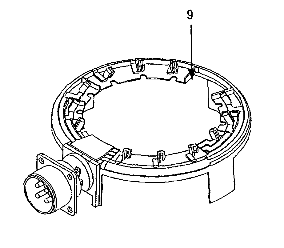
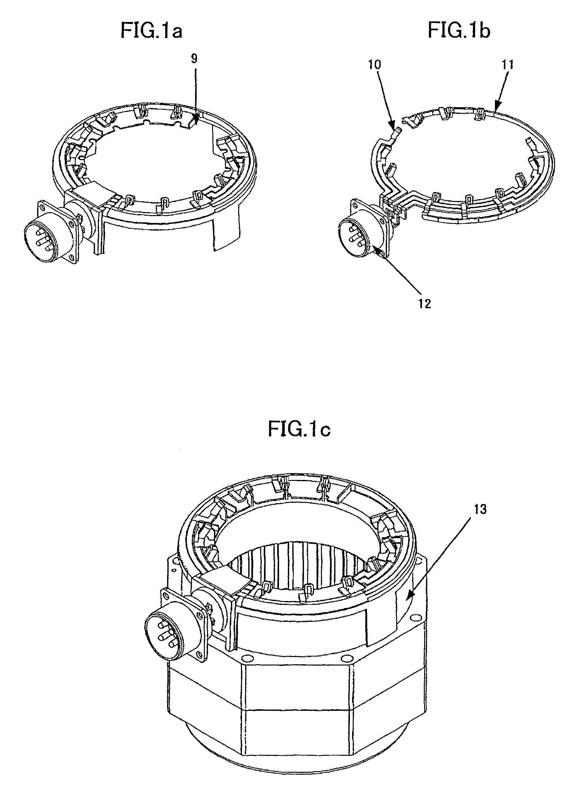
[0029]FIGS. 1a-1c show examples of coil connecting structures that are one embodiment of the present invention. Conductors 11 are formed of a conductively caulkable material such as copper. One end of each conductor 11 is formed into the shape of a terminal as a terminal-shaped portion 10, and the other end is mounted on a power input member (connector) 12. The conductors 11 are formed so as to conform to the shape of coil ends of a stator coil 13 and maintain that shape, and therefore the conductors 11 do not protrude outside the electric motor.

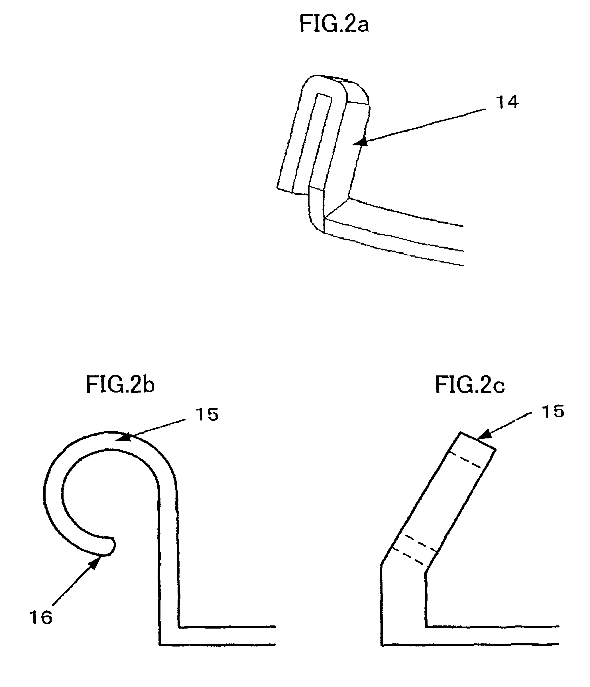
[0030]FIGS. 2a-2c show expanded views of the terminal-shaped portion 10 formed in one end of the conductors 11. The shape of the terminal-shaped portion 10 need only be such as to accommodate lead terminals of the coils and enable them to be temporarily retained in place, and FIG. 2a shows the terminal-shaped portion 10 as a U-shaped terminal 14. FIG. 2b shows the terminal-shaped portion 10 as an arc-shaped terminal 15. FIG. 2b shows a front...


PUM

PropertyMeasurementUnit
electric poweraaaaaaaaaa
coil connecting structureaaaaaaaaaa
angleaaaaaaaaaa

Abstract

An electric motor that does not provide new terminals for carrying out conductive caulking, and further, facilitates the work of using a conductive caulking machine. An electric motor coil connecting structure that connects conductors connected to a power input member and lead terminals of coils by conductive caulking and connects the power input member and the lead terminals of the coil electrically. One end of each of the conductors is formed into a terminal-shaped portion in which the lead terminals of the coil can be fitted and temporarily retained. The lead terminals of the coil are fitted in the terminal-shaped portion of the conductors and temporarily retained, and connected by conductive caulking.

Description

BACKGROUND OF THE INVENTION[0001]1. Field of the Invention[0002]The present invention relates to an electric motor, and more particularly to an electric motor in which an electrical connection between lead terminals of coils such as stator windings and a power input member (connector) to which an electric power is inputted is facilitated for easy assembly, a connecting structure in the electric motor, a connecting method and a set of conductors for use in the electric motor.[0003]2. Description of Related Art[0004]In an electric motor having a structure that connects ends of coils wound around a stator to a power input member (connector) or a terminal block, conventionally, as shown in FIG. 8, the ends 2 of the coils are pulled out from a connector mounting 1, stripped, and soldered directly to the connector 3.[0005]In addition, a technique is known in which, as shown in FIG. 9, conductors 6 fixedly mounted on an insulator 5 are mounted on the power input unit (connector) 4 in advan...

Claims


Application Information

Patent Timeline
Patent Type & Authority Patents(United States)
IPC IPC(8): H02K11/00H01F27/29H01F7/06H01R43/00H02K15/00H02K3/48H02K3/46H01H11/00H02B1/20
CPCH02K2203/09H02K3/50H02K5/225H02K15/0062H02K3/38
Inventor YAMAMOTO, TOMONAGAUEMATSU, HIDETOSHI
Owner FANUC LTD
Why Eureka
Try Eureka