Display device

a display device and liquid crystal technology, applied in the field of liquid crystal display devices, can solve the problems of no effective means for the efficient use of light output, and the problem of field sequential systems that are known to pose a problem, etc., to achieve the effect of reducing the generation of heat, and increasing luminous energy

Inactive Publication Date: 2010-12-14
AVAGO TECH INT SALES PTE LTD
View PDF17 Cites 7 Cited by
  • Summary
  • Abstract
  • Description
  • Claims
  • Application Information

AI Technical Summary

Benefits of technology

[0010]A bright display is realized with low energy consumption and minimal generation of heat because there is a relative increase in the luminous energy of each light used in the display. In particular, it becomes possible to greatly reduce the number of light-emitting diodes for green emission by increasing the green luminous energy, and this leads to a reduction in cost, a reduction in power consumption, and a reduction in the amount of heat generated. Moreover, it becomes possible to reduce the drive current of the red, green, and blue light-emitting diodes by increasing the luminous energy of each of the diodes, and power consumption and the amount of heat generated can be reduced while keeping the illumination constant. Each pixel can be shared by two colors and the resolution of at least green images can therefore be brought to twice the resolution of the red and blue images.

Problems solved by technology

However, field sequential systems are known to pose a problem in terms of a color disruption that is attributed to mistiming of emissions, and the like.
Nevertheless, there is a need for further modification because there is no effective means for the efficient use of light output from an emission means in order to lower the energy consumption while maintaining a relatively strong brightness.
For instance, the display switching speed of the liquid crystal display is not fast enough to follow the switching between the emission means when the above-mentioned subfield is further divided into six fields; therefore, it is very difficult to realize a practical display device.

Method used


Image

  • Display device
  • Display device
  • Display device

Examples


Embodiment Construction

[0015]A preferred embodiment of the display device of the present invention will now be described in further detail while referring to the drawings.

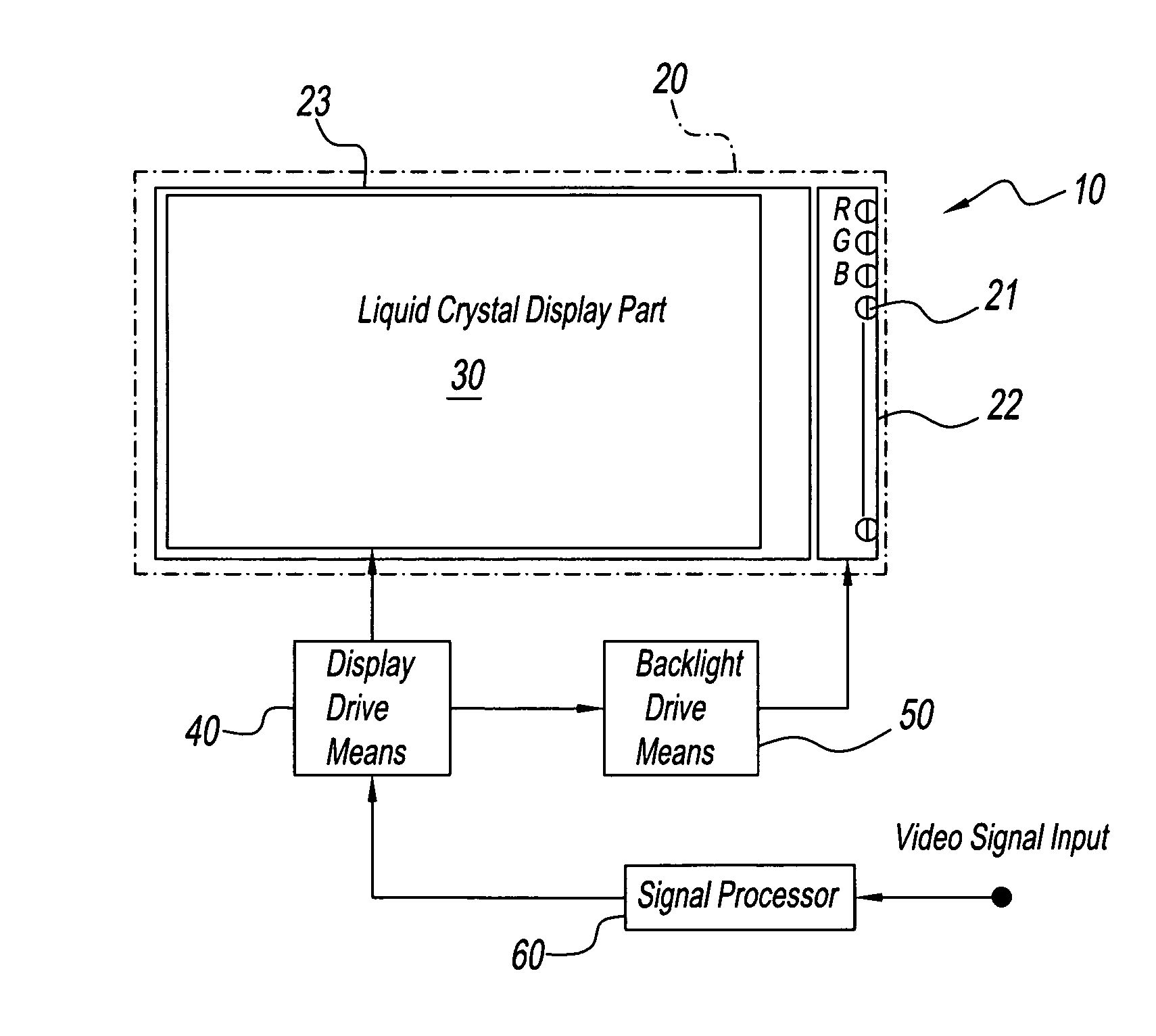
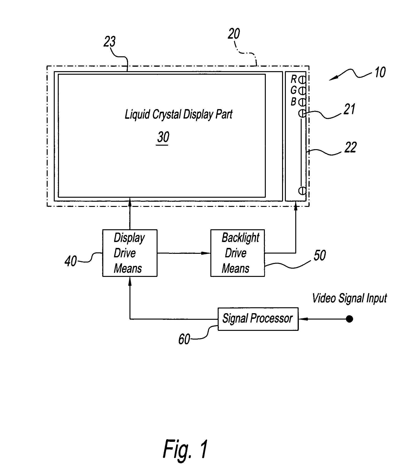
[0016]FIG. 1 is a drawing showing each structural element of the display device of the present invention. A display device 10 of the present invention comprises a display means 20 consisting of a liquid display module 23 and a backlight source 22 that supplies backlight from behind the module. Although not illustrated, there is usually a light guide on the back of liquid display module 23, and light from light source 22 is radiated onto this light guide. The light guide feeds backlight from behind liquid crystal display module 23 over the entire surface of a display part 30. Liquid crystal display module 23 is driven by a drive means 40 and the screen thereof is displayed. Drive means 40 is separate from display means 20 in FIG. 1, but it can also be a single cohesive unit with liquid crystal display module 23 as a part of display means ...


PUM


Abstract

A display device comprises a light source consisting of three emission elements, each of which emits light of different wavelength regions corresponding to the respective colors of red, green and blue, and a display module consisting of a display part wherein each pixel has two types of color filters that transmit red and green light and green and blue light, respectively. One frame of video signals is split during display to become two subframes and it is possible to alternately emit for each subframe green light, which is transmitted through both color filters, and red and blue light, each of which is transmitted through only one filter.

Description

FIELD OF THE INVENTION[0001]The present invention relates to a liquid crystal display device for color display that is widely used in televisions, personal computer monitors, laptop monitors, mobile telephones, game players, and the like, and in particular, relates to a display device having a light source that is capable of independently controlling R (red), G (green), and blue (blue) emission.DISCUSSION OF THE BACKGROUND ART[0002]Liquid crystal display devices normally consist of a light source that is placed at the back surface of a liquid crystal panel. Conventional light sources often have a cold cathode ray tube or other lamp as the emission means, but light sources that use a light-emitting diode or other semiconductor element as the light-emitting means are now used for practical purposes (for instance, refer to JP Unexamined Patent Application (Kokai) 2001-92,414, and JP Unexamined Patent Application (Kokai) 2001-332,764).[0003]On the other hand, a typical color display sys...

Claims


Application Information

Patent Timeline
Patent Type & Authority Patents(United States)
IPC IPC(8): G09G3/36
CPCG09G3/3413G09G3/3607G09G2310/0235
Inventor SEKIGUCHI, NOBUTOSHI
Owner AVAGO TECH INT SALES PTE LTD
Why Eureka
Try Eureka