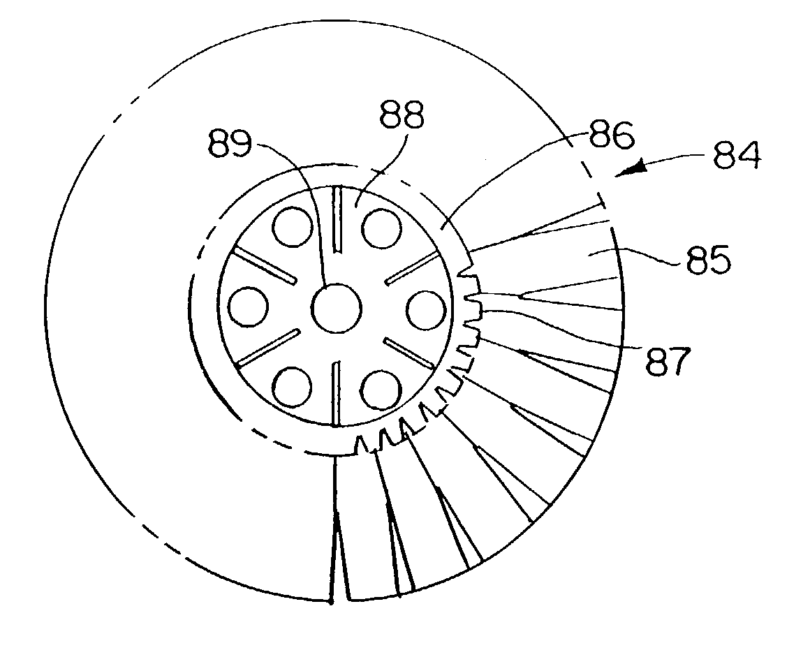
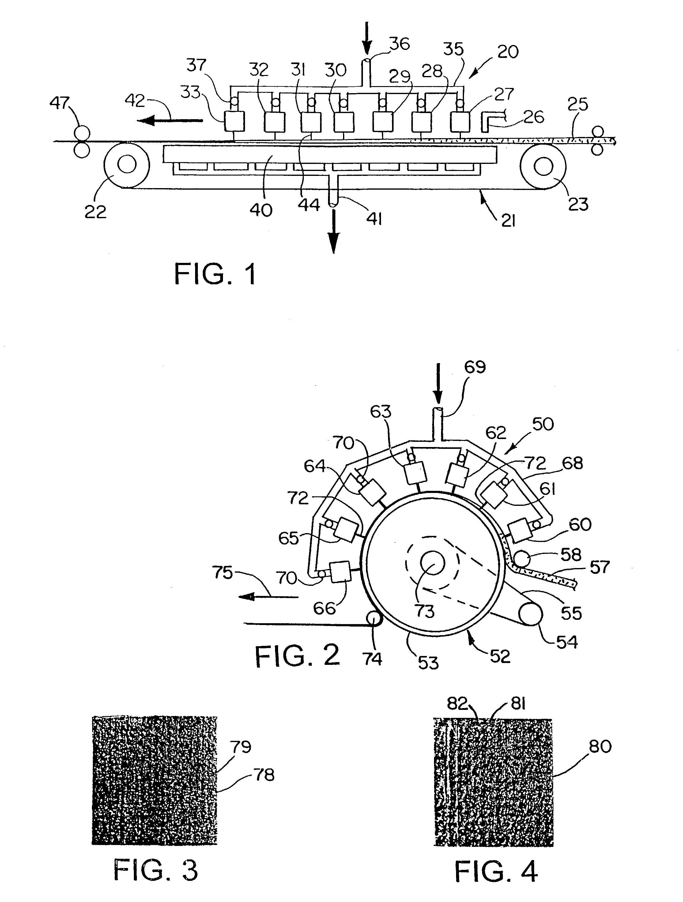
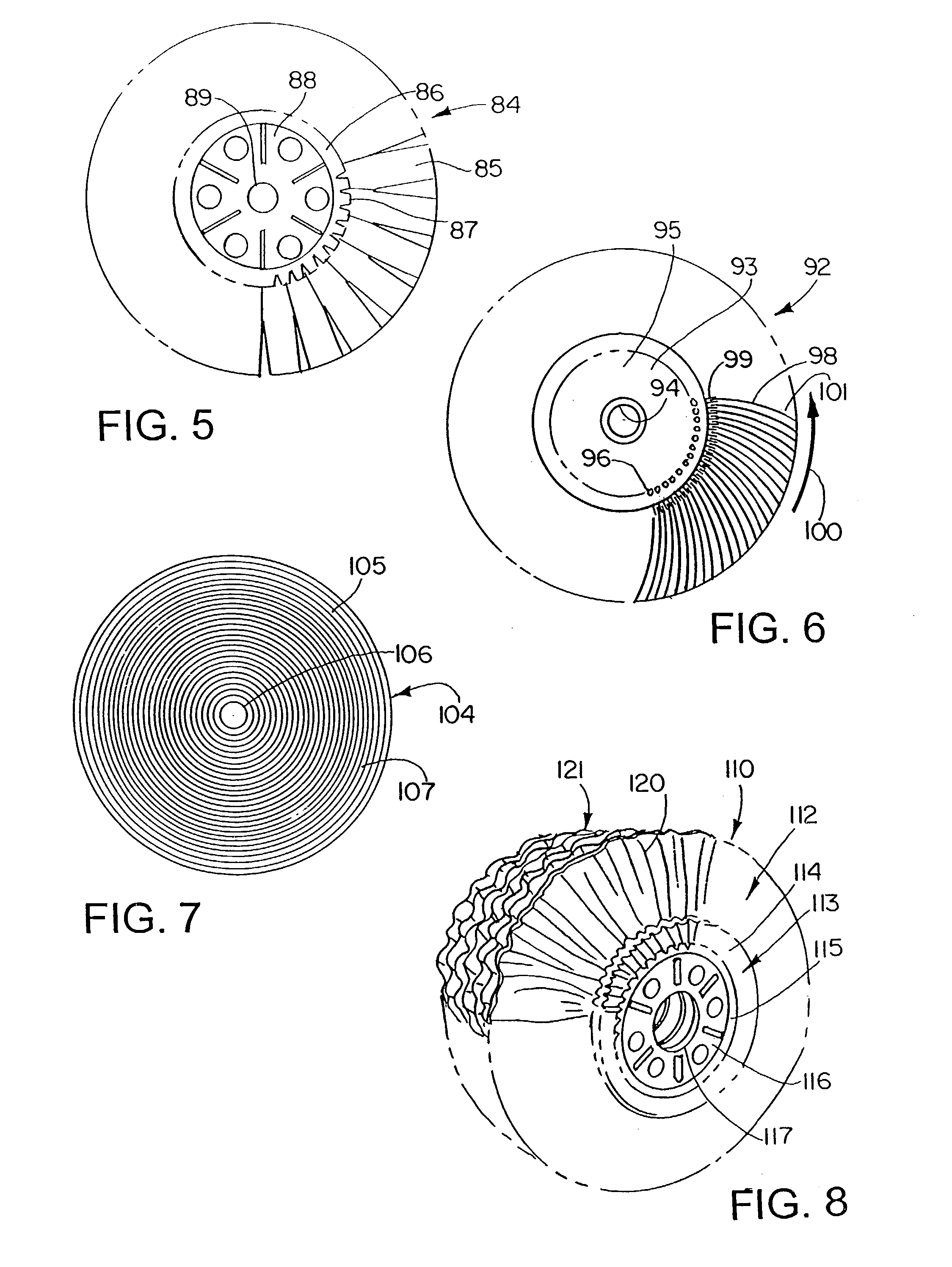
Buffing tools and methods of making

a tool and tooling technology, applied in the field of tooling tools and methods of making, can solve the problems of significant heat, heat can be deleterious to both, affect the treatment and its application, etc., and achieve the effects of long working life, good wear resistance, and high heat application

Inactive Publication Date: 2007-01-09
JASON INC
View PDF4 Cites 6 Cited by
  • Summary
  • Abstract
  • Description
  • Claims
  • Application Information

AI Technical Summary

Benefits of technology

[0019]It is a principal object of the invention to provide a buff which will not generate excessive heat adversely affecting the work, or treatments, or the buff itself, and which will have a substantially longer working life. Yet it is also important that the buff have good wear resistance in high heat application. It is also important that the fabric of the buff be light weight a

Problems solved by technology

The movement of the fabric over the work may create significant heat both in the work and in the fabric.
It has been found generally that such heat can be deleterious to both.
Regardless, excess heat may adversely affect the treatment and its application and makes it difficult to achieve the results desired.
In some cases a liquid coolant may be used similar to machine tool operations, but this creates problems in circulation and filtration.
Such systems are usually a costly mess.
As far as the cloth or fabric is concerned

Method used


Image

  • Buffing tools and methods of making
  • Buffing tools and methods of making
  • Buffing tools and methods of making

Examples


example 1

[0055]

COMPOSITION: 100% POLYESTER PAD DYED MUSTARDDESIGN: OCTAGON / SQUARESPHYSICAL PROPERTIESWEIGHT, oz / yd23.5THICKNESS (1 ply, mils)25.6TENSILE, lbsGRAB STRIP EN DIN, N / 50 mmMD93.443.81647.1CD72.531.71396.7ELONGATION %MD41.244.338.7CD62.767.857.4MULLEN BURST, (psi)134TABER ABRASION (cycles to fail)3000+TEAR STRENGTHElmendorf, gmsTrapezoid, lbsMD278237.3CD324848.3ABSORBENCYCAPACITY (%)470TIME (sec)1.8

example 2

[0056]

COMPOSITION: 100% POLYESTER HIGH ABRASIVE FINISHDESIGN: MINI-HERRINGBONEPHYSICAL PROPERTIESWEIGHT, oz / yd23.7THICKNESS (1 ply, mils)36TENSILE, N / 50 mm to DIN EN 29 073MD1947.0CD1625.0ELONGATION, % to DIN EN 29 073MD76.0CD108.7ABSORBENCYCAPACITY, %649TIME, sec.1.6TABER ABRASION (cycles to fail) 4000+MULLEN BURST, psi75.2AIR PERMEABILITY, 6 mm348SURFACE ABRASION @ 12 kPA pressure, cycles45,000BS 5691:1988, Martindale

example 3

[0057]

COMPOSITION:100% PETDESIGN: OCTAGON / SQUARESWEIGHT, oz / yd23.5GRAB TENSILE, N / 50 mm to DIN EN 29 073MD1538.5CD1312.0ELONGATION, % to DIN EN 29 073MD38.8CD65.4GRAB TENSILE, lbs ASTM D5034MD95.38CD65.24ELONGATION, %MD37.04CD66.96STRIP TENSILE, lbs ASTM D5035MD35.25CD28.26ELONGATION, %MD39.23CD66.21THICKNESS, 1 ply, mils ASTM D572921.5ELMENDORF TEAR, grams ASTM D5734MD1393CD1213ABSORBENCY ASTM D1117 (Section 21)CAPACITY, %497TIME, sec.1.3MULLEN BURST, psi ASTM D461 (Section 13)134.0AIR PERMEABILITY, cfm / in. ASTM D737199 (4 mm)TABER ABRASION, cycles ASTM D3884 1100+SURFACE ABRASION @ 12 kPA pressure, cycles45,000BS 5690:1988, Martindale

[0058]It is noted that all three of these specific examples have both machine and cross-direction tensile strengths well in excess of the minimal tensile strengths specified in the strength specifications. Also the fabrics are light weight being within the weight per square yard range of the specifications.

[0059]The fabric with the extremely high mech...


PUM

PropertyMeasurementUnit
Timeaaaaaaaaaa
Diameteraaaaaaaaaa
Fractionaaaaaaaaaa

Abstract

A buff is made from a non-woven fabric where the fibers are first carded and formed into a fairly thick fleece. The fleece is passed over a topographical surface on, for example, a moving belt or a drum. The fleece is subject to a bow-tie hydroentanglement process where many fine jets of water entangle the fibers on the topographical surface. Excess water is vacuumed from the system. The fabric is dried and chemically treated. With the fabric a variety of buffing tools are made, in wheel, belt or roll form. Tests against standard and mill treatment buffs show a remarkably lower fabric weight loss percentage and lower or normal operating temperatures. The fabric has exceptional mechanical strength having a tensile strength in excess of 650 N/50 mm according to DIN 29073/3. Preferably the fabric has a tensile strength of at least 1,000 N/50 mm in the machine direction and in excess of 900 N/50 mm in the cross direction according to such DIN.

Description

CROSS-REFERENCE TO RELATED APPLICATION[0001]This application is a division of U.S. patent application Ser. No. 09 / 703,087, filed Oct. 31, 2000 now U.S. Pat. No. 6,595,843.DISCLOSURE[0002]This invention relates generally as indicated to a buffing tools and methods of making such tools, and more particularly to buffing tools having improved fabric or cloth greatly enhancing the efficiency, useful life, and productivity of the tool.BACKGROUND OF THE INVENTION[0003]Buffing tools probably are embodied most commonly in the form of a wheel. The wheel includes one or more discs or plates providing an arbor hole. The cloth or fabric is secured to and projects radially from the discs. The projecting edge of the fabric is the working face of the tool. Several layers or plys of fabric may be provided for each wheel and the fabric may be folded, bunched, puckered, or pleated so that the fabric edge zig-zags back and forth at the face, and the working face of the tool may be substantial axially w...

Claims


Application Information

Patent Timeline
IPC IPC(8): B24D11/00B24D13/08D04H1/46D04H1/70D04H1/72
CPCB24D11/00B24D13/08D04H1/72D04H1/70D04H1/465D04H1/495D04H18/04
Inventor WEBER, ROBERT J.
Owner JASON INC
Why Eureka
Try Eureka