Optical compensation layer-attached polarizing plate, liquid crystal panel, liquid crystal display, image display, and method for producing optical compensation layer-attached polarizing plate

a technology of optical compensation layer and polarizing plate, which is applied in the direction of optics, polarising elements, instruments, etc., can solve the problems of unevenness or irregularities, large overall thickness of optical compensation layer attached polarizing plate, and easy to occur unevenness or irregularities, so as to reduce the number of processes in the lamination of optical compensation layers and improve productivity. , the effect of reducing the thickness

Inactive Publication Date: 2010-12-14
NITTO DENKO CORP
View PDF15 Cites 21 Cited by
  • Summary
  • Abstract
  • Description
  • Claims
  • Application Information

AI Technical Summary

Benefits of technology

[0009]It is an object of the invention to provide an optical compensation layer-attached polarizing plate with which viewing angle compensation and broadband circular polarization can be achieved for VA mode liquid crystal cells, with which a thin structure is possible, and with which uneven heat-up can be reduced. It is another object of the invention to provide an optical compensation layer-attached polarizing plate with which light leakage can be suppressed to be small when black viewing is displayed. It is a yet another object of the invention to provide a method for producing such an optical compensation layer-attached polarizing plate.
[0018]In the optical compensation layer-attached polarizing plate of the invention, both the optical compensation layers (1) and (2) contain a resin with a photoelastic coefficient absolute value of at most 2.0×10⁻¹¹ m2 / N so that even when contraction stress is caused by heating, the retardation can hardly be changed and heat-induced unevenness can be suppressed. In addition to the use of the material with a small photoelastic coefficient, the number of laminated layers is reduced as mentioned above, so that the number of shrinkable films and pressure-sensitive adhesive layers are reduced. Thus, uneven heat-up can be significantly reduced at the time of heating.
[0033]In the optical compensation layer-attached polarizing plate of the invention, the optical compensation layers (1) and (2) can provide viewing angle compensation and broadband circular polarization. Thus, the thickness can be reduced so that the number of processes in the lamination of optical compensation layers can be reduced, with which an improvement in productivity and a reduction in cost can be provided. In the production method as stated above, the polarizing plate and the optical compensation layer (2) are each continuously conveyed from a roll or the like, while the optical compensation layer (1) is interposed between the conveyed materials at a specific angle to form a laminate, so that a further improvement in productivity and a further reduction in cost are possible. Thereafter, the resulting optical compensation layer-attached polarizing plate may be subjected to a punching process to give final product pieces.

Problems solved by technology

For example, conventional reflective or transflective VA mode liquid crystal displays have the problem of contrast reduction, because they can cause light leakage when black viewing is displayed.
An optical compensation layer-attached polarizing plate with a large overall thickness is undesirable for liquid crystal displays, which should be designed to be thin.
Liquid crystal displays can be placed in various environments of severe temperature or the like, and particularly under heated conditions, unevenness or irregularities can easily occur due to film shrinkage and the like.

Method used


Image

  • Optical compensation layer-attached polarizing plate, liquid crystal panel, liquid crystal display, image display, and method for producing optical compensation layer-attached polarizing plate
  • Optical compensation layer-attached polarizing plate, liquid crystal panel, liquid crystal display, image display, and method for producing optical compensation layer-attached polarizing plate
  • Optical compensation layer-attached polarizing plate, liquid crystal panel, liquid crystal display, image display, and method for producing optical compensation layer-attached polarizing plate

Examples


example 1

Polarizing Plate

[0107]A polyvinyl alcohol film (VF-PS manufactured by Kuraray Co., Ltd.) was stretched at a stretch ratio of about 6 in an aqueous solution containing iodine and potassium iodide and then dried to form a 30 μm-thick belt-shaped polarizer. A triacetyl cellulose film (25 μm in thickness) manufactured by Fuji Photo Film Co., Ltd. (serving as a belt-shaped protective film) was bonded to each of both sides of the polarizer with a polyvinyl alcohol adhesive so that an about 100 μm-thick belt-shaped polarizing plate (1300 mm in width) was prepared. In addition, an acrylic pressure-sensitive adhesive layer (20 μm in thickness) for adhering to the optical compensation layer (1) and a separator were sequentially formed on one side of the polarizing plate, having the protective film on the other side.

(Optical Compensation Layer (1))

[0108]An about 60 μm-thick belt-shaped film made of a norbornene resin with a photoelastic coefficient absolute value of 3.1×10⁻¹² (m2 / N) was uniaxi...

example 2

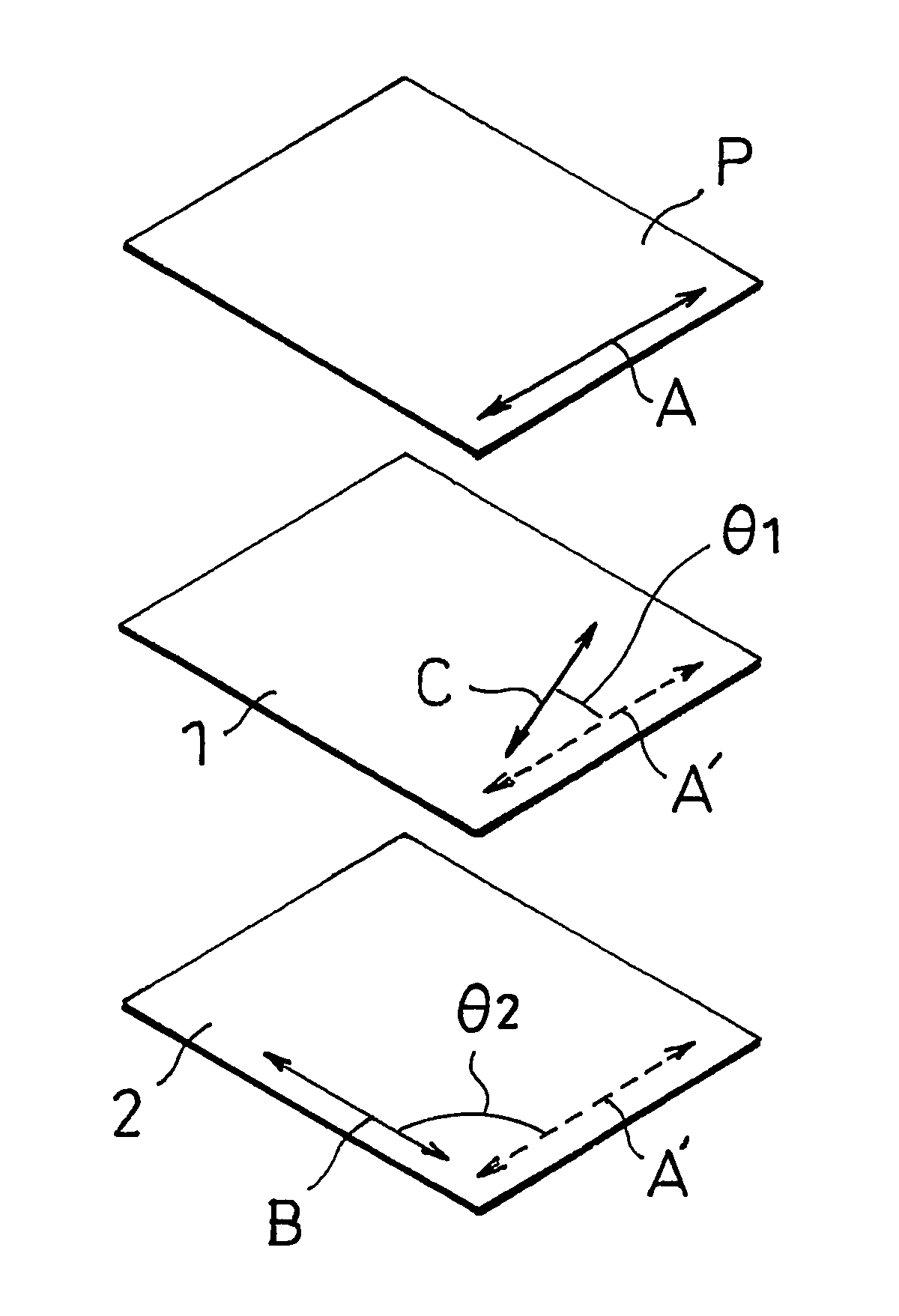
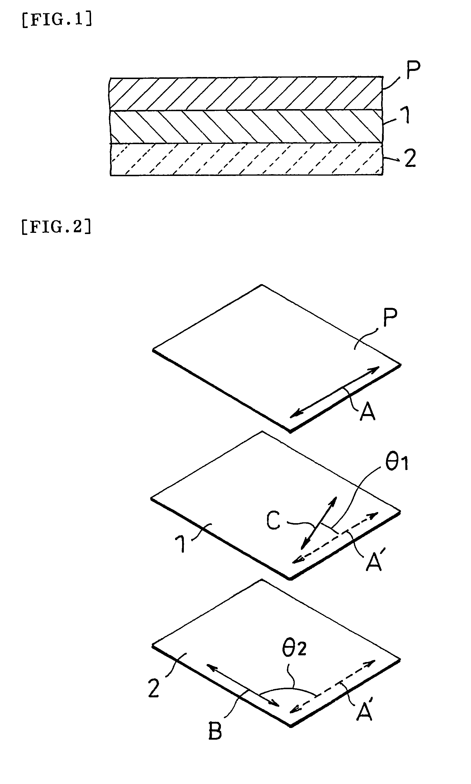
[0129]An optical compensation layer-attached polarizing plate was prepared using the process of Example 1, except that the optical compensation layer (1) was interposed between the polarizing plate (P) and the optical compensation layer (2) in such a manner that the slow axis C of the optical compensation layer (1) made an angle of 10° with the absorption axis A of the polarizing plate (P).

example 3

[0130]An optical compensation layer-attached polarizing plate was prepared using the process of Example 1, except that the optical compensation layer (1) was interposed between the polarizing plate (P) and the optical compensation layer (2) in such a manner that the slow axis C of the optical compensation layer (1) made an angle of 14° with the absorption axis A of the polarizing plate (P).


PUM


Abstract

An optical compensation layer-attached polarizing plate including a polarizing plate, an optical compensation layer and another optical compensation layer that are laminated in this order, wherein the optical compensation layer has the relation nx1>ny1=nz1, including a resin with a photoelastic coefficient absolute value of at most 2.0×10⁻¹¹ m2 / N, and has an in-plane retardation (nx1−ny1)d1 in the range of 200 nm to 300 nm, the optical compensation layer has the relation nx2>ny2>nz2, including a resin with a photoelastic coefficient absolute value of at most 2.0×10⁻¹¹ m2 / N, and has an in-plane retardation (nx2−ny2)d2 in the range of 90 nm to 160 nm, a slow axis of the optical compensation layer makes an angle of 10° to 30° with an absorption axis of the polarizing plate, and a slow axis of the optical compensation layer makes an angle of 75° to 95° with the absorption axis of the polarizing plate.

Description

TECHNICAL FIELD[0001]The invention relates to an optical compensation layer-attached polarizing plate and a manufacture method thereof. The optical compensation layer-attached polarizing plate of the invention is useful as a circularly polarizing plate and may be used alone or in combination with any other optical film to form a variety of optical films.[0002]The invention also relates to a liquid crystal panel using the optical compensation layer-attached polarizing plate and to a liquid crystal display using the liquid crystal panel. In particular, the optical compensation layer-attached polarizing plate of the invention is effective for use in liquid crystal panels or liquid crystal displays using vertical alignment (VA) mode liquid crystal cells. In particular, the optical compensation layer-attached polarizing plate of the invention is effective for reflective or transflective VA mode liquid crystal cells. The optical compensation layer-attached polarizing plate may be used for...

Claims


Application Information

Patent Timeline
Patent Type & Authority Patents(United States)
IPC IPC(8): G02B5/30
CPCG02B5/3033G02F1/13363G02F2001/133531G02F2202/40G02F2413/02G02F2413/07G02F2413/08G02F2413/12G02F2413/13G02F1/133531G02B5/30G02F1/1335
Inventor CHIBA, TSUYOSHIKAWAMOTO, IKUOKAWAHARA, SATORUHATA, MASAHIROKOZONOI, NOBUYUKISHUTO, SHUNSUKE
Owner NITTO DENKO CORP
Why Eureka
Try Eureka