Paint pad with adjustable handle

a technology of adjustable handle and paint pad, which is applied in the direction of manufacturing tools, cleaning equipment, carpet cleaners, etc., can solve the problems of affecting painting quality, difficult to control the operating angle, and fixed but not flexible connection, so as to facilitate operation and reduce painting cost. , the effect of increasing working efficiency

Inactive Publication Date: 2010-12-21
LU JIANXIN
View PDF4 Cites 9 Cited by
  • Summary
  • Abstract
  • Description
  • Claims
  • Application Information

AI Technical Summary

Benefits of technology

[0005]A paint pad with adjustable handle comprises a handle; a pad unite that includes a pad support body and a pad holder plate; the pad holder plate is connected to the bottom of the pad support body; wherein the pad support body has a handle groove on the top; a orientation part is under the groove, its up surface has a plurality of orientation teeth; the handle with plurality of adjusting teeth at the end of handle is located in the groove; a knob on the top of the pad support body can adjust the relationship between the orientation teeth and adjusting teeth. The orientation part can be designed as an individual part, or as one part of the pad support body located on the bottom of the handle groove; the handle connects with the pad support body by an axle to make it easy operation by operators, the new tool meets different operating position and angle requirements. There is a handle groove on the top of the pad support body, the connecting end of the handle embeds into the handle groove to limit its left & right swing but allow its up & down vertical pivotal movement during operation. In addition, this structure is possible to fix the handle in a position when operator sponges paint, so that it will be easy for operator to erase superabundance, to avoid dripping everywhere. If operator needs handle to have a fixed position angle relating to the pad support body during painting, he can tighten it by turning the knob to engage the orientation teeth onto the adjusting teeth tightly, this movement generates enough engaging force to guarantee stable angle between the pad support body and the handle during operation. If the operator needs the handle having a pivotal movement freely, he can just unscrew the knob to free the orientation teeth with the adjusting teeth.
[0016]This invention can allow the handle to have up & down vertically pivotal movement but not left & right swing relating to the pad support body and the painting surface. When the knob is tightened, the orientation teeth engage to the adjusting teeth, and this movement generates enough engaging force to guarantee stable angle between the pad support body and the handle during operation. When the knob is loosed, the orientation teeth and adjusting teeth are apart, thus the handle can move up & down freely, this makes operator easy to handle and operate, help to increase painting quality; also this design makes the pad holder plate easy exchangeable, and the pad can absorb more paint, it is quite usable when operator paints the corner or the adjacent areas with different colors, and reduce the cost significantly.

Problems solved by technology

The fixed but not flexible connection brings lot of inconveniencies.
When the painting pad is used in painting wall corners or adjacent areas with different colors, operator need to change the angle between the handle and pad, but the traditional pant pad can not meet the requirements, thereby to influence the processing schedule and painting quality.
However, this kind of paint pad has its flaws, the operator can not orientate the handle or pad, it is easy to slid and hard to control the operating angle, the painting quality is affected.
Therefore, this kind of paint pad is s till fallible and instable, which can influence the painting route and uniformity, and reduce painting quality.

Method used


Image

  • Paint pad with adjustable handle
  • Paint pad with adjustable handle
  • Paint pad with adjustable handle

Examples


first embodiment

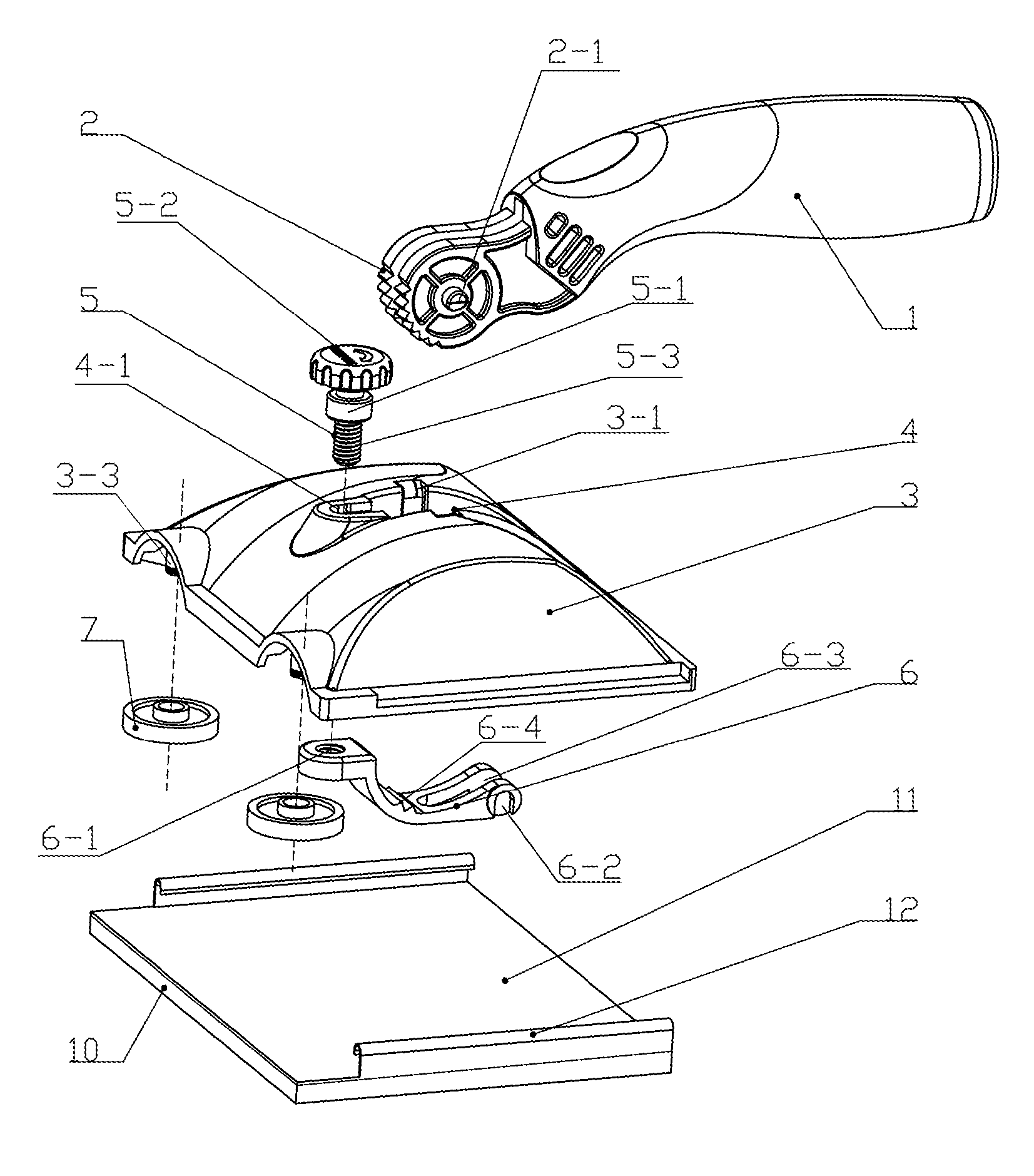
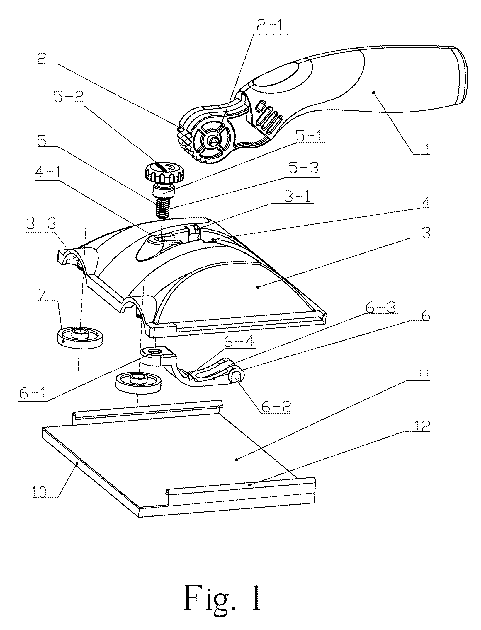
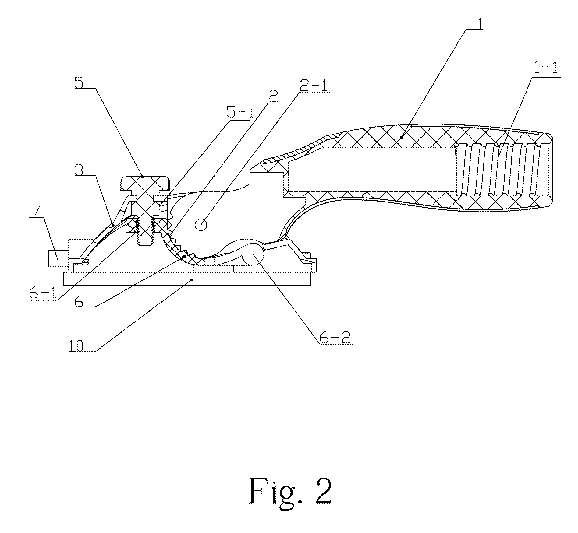
[0022]FIGS. 1 and 2 show the present invention.

[0023]As FIGS. 1 and 2 show, a paint Pad with Adjustable Handle has a handle 1 and a paint pad unite, which includes a pad support body 3, and pad holder plate 11. The Handle 1 is connected with the top of the pad support body 3 by axis 2-1, the end of handle near the axis is a the cylinder shape that is perpendicular to the direction of handle, quarter of the cylinder has plurality of adjusting teeth 2, a transverse axis 2-1 at the center of the cylinder; the handle 1 wraps with soft material, and a screw bore 1-1 is in its end, the handle 1 can have different length, also can attach a long staff into the screw bore 1-1 to increase painting area. There is a handle groove 4 which has the direction same as handle 1 on the top of the pad support body 3; a connecting channel 4-1 which is in front of the handle groove 4 is on the top of the pad support body 3 too; the connecting channel 4-1 is through with the handle groove 4; the inboard s...


PUM

PropertyMeasurementUnit
angleaaaaaaaaaa
angleaaaaaaaaaa
shapeaaaaaaaaaa

Abstract

A paint pad with adjustable handle belong to painting tool field, includes a handle; a pad unite that includes a pad support body and a pad holder plate, the pad holder plate is connected to the bottom of the pad support body; wherein the pad support body has a handle groove on the top; a orientation part is under the groove, its up surface has a plurality of orientation teeth; the handle with plurality of adjusting teeth at the end of handle is located in the groove; a knob on the top of the pad support body can adjust the relationship between the orientation teeth and adjusting teeth. The conventional paint pad is fallible and instable for keeping stable angle between the handle and pad unite, it influences the painting route and uniformity, and reduces painting quality. The paint pad of the present invention allows the handle to have up & down vertically pivotal movement but not left & right swing; though the knob to adjust the engaging force between teeth, therefore, keep the right needed angle for stable operation. The new paint pad possesses advantages of easy in changing working situation, comfortable holding, big amount of absorbing paint, speedy painting, high quality in painting of corner wall areas and area with different colors and exchangeable of paint pad.

Description

CROSS REFERENCE TO THE RELATED PATENT APPLICATION[0001]This patent application claims the priority benefit of the Chinese patent application No. 200620102340 filed on Apr. 4, 2006.FIELD OF THE INVENTION[0002]This invention relates to an innovative technology for the flat painting tool, especially a paint pad with adjustable handle.BACKGROUND OF THE INVENTION[0003]As a convenient and practical painting tool, flat painting brush and painting pad still occupy irreplaceable status and role when people paint the wall or other surfaces. Currently, the joint methods for the pad unite and pad handle can be traditional fixation or universal coupling connection. In the traditional one, the pad unite is fixed with its handle. The fixed but not flexible connection brings lot of inconveniencies. When the painting pad is used in painting wall corners or adjacent areas with different colors, operator need to change the angle between the handle and pad, but the traditional pant pad can not meet the...

Claims


Application Information

Patent Timeline
Patent Type & Authority Patents(United States)
IPC IPC(8): A47K7/02
CPCB05C17/00
Inventor LU, JIANXIN
Owner LU JIANXIN
Why Eureka
Try Eureka