Light collection assembly with self-retaining lens in electro-optical reader

a technology of electro-optical reader and assembly, which is applied in the direction of mountings, sensing record carriers, instruments, etc., can solve the problems of large-sized readers, difficult to achieve economically when using adhesives, and large assembly and manufacturing costs of readers, so as to reduce assembly and manufacturing costs, the effect of high degree of accuracy

Active Publication Date: 2010-12-21
SYMBOL TECH LLC
View PDF6 Cites 1 Cited by
  • Summary
  • Abstract
  • Description
  • Claims
  • Application Information

AI Technical Summary

Benefits of technology

[0008]In accordance with one feature of this invention, a single collection lens of fixed focus is assembled with a high degree of accuracy relative to the sensor, without adhesives, and retains itself in the assembled position. This reduces assembly and manufacturing costs and promotes the use of the reader as a miniature component in a non-stand-alone apparatus, such as the coffee maker described above, or a myriad of other apparatuses, such as a telephone, mobile computer, or the like where space is at a premium.
[0010]Preferably, the frame resembles a sawhorse and includes a cross beam extending linearly along a longitudinal direction. The lens extends from the beam. The legs are splayed and diverge from the beam in a direction transverse to the longitudinal direction. At least some of the legs yield resiliently from an initial unstressed condition during insertion of the frame into the chassis to a stressed condition in the assembled position, thereby anchoring the frame within the compartment due to the constant urging of the legs against the compartment walls back to the initial condition. The frame includes reinforcement sections integral with the beam and others of the legs, for reinforcing the other legs to prevent their breakage.

Problems solved by technology

As advantageous as such moving beam and imaging readers are in capturing data as stand-alone data capture systems, such a reader can be a relatively large and expensive component in assembly and manufacture, especially if it is installed in an apparatus in which the reader is a subsystem.
This is difficult to achieve economically when an adhesive is employed.
A manufacturer is not likely to use an uneconomic, large-sized reader, especially in an apparatus with little room to spare.

Method used


Image

  • Light collection assembly with self-retaining lens in electro-optical reader
  • Light collection assembly with self-retaining lens in electro-optical reader
  • Light collection assembly with self-retaining lens in electro-optical reader

Examples


Embodiment Construction

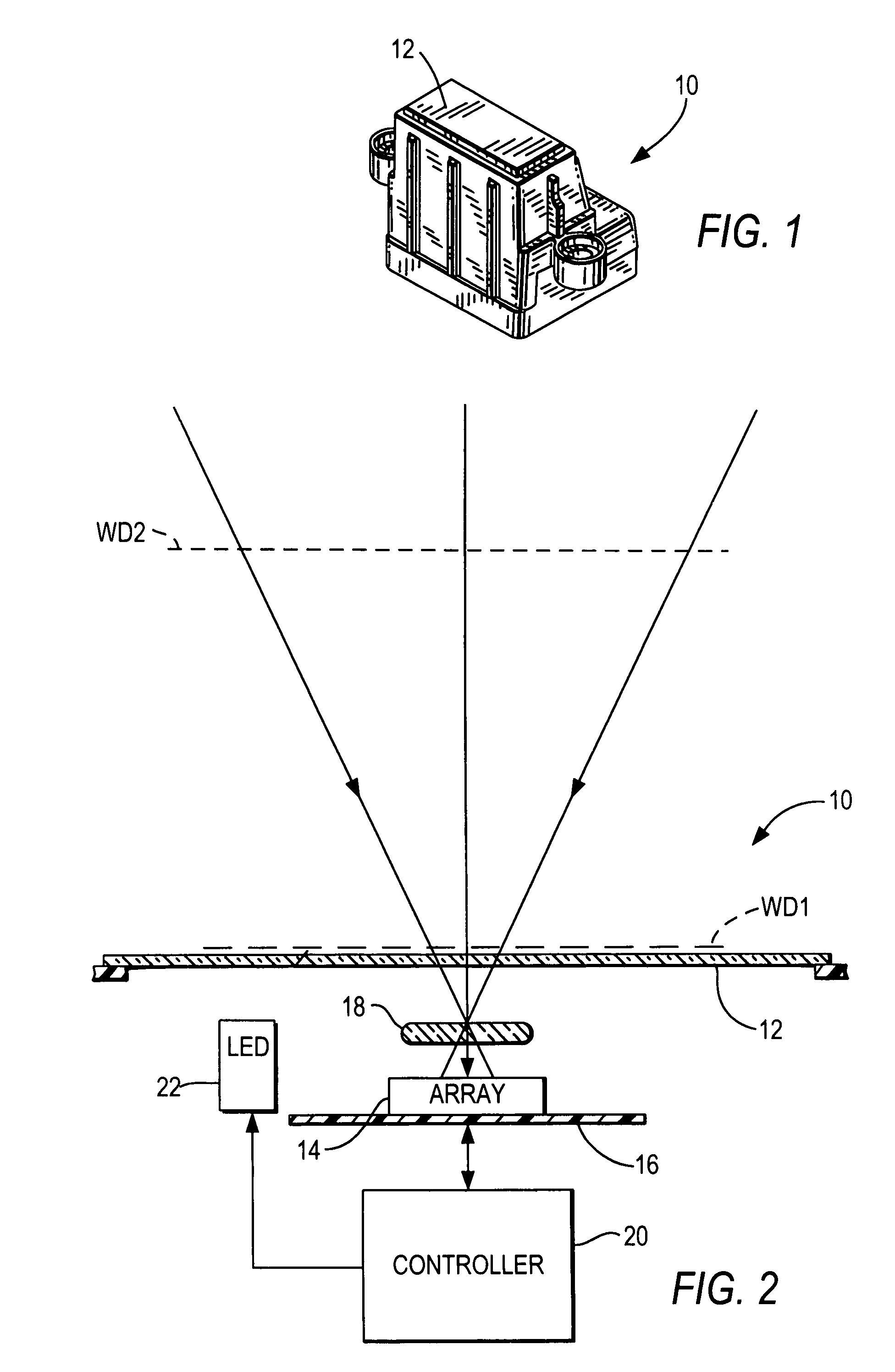
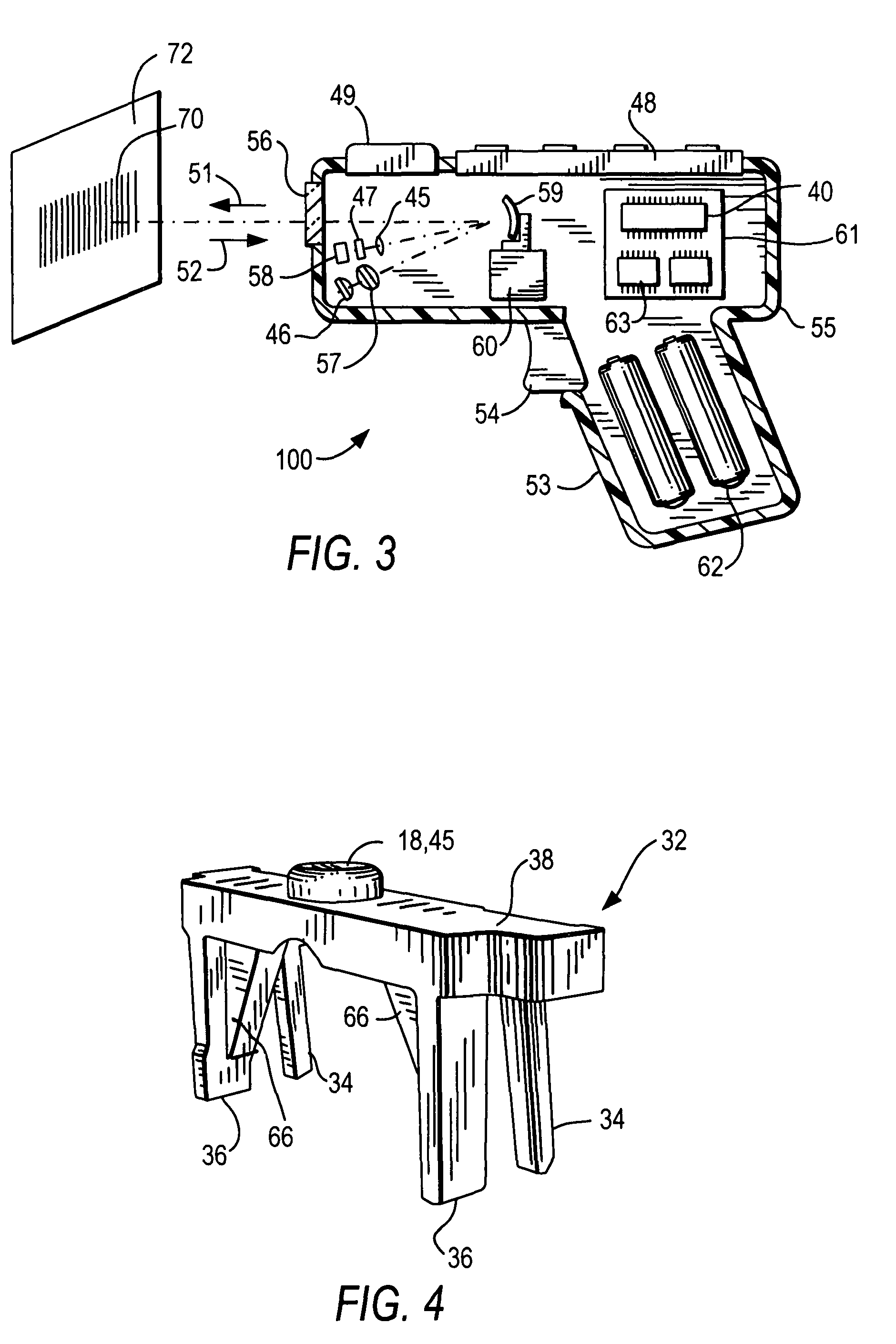
[0021]Reference numeral 10 in FIG. 1 generally identifies a data capture system or an electro-optical imaging reader for electro-optically reading indicia, such as bar code symbols, by capturing illumination and / or ambient light reflected or scattered from the symbols with an array of image sensors. In use, an operator presents each symbol to be read to a window 12. The reader 10 can be used as a stand-alone device, but has been especially designed herein to be portable, miniature, lightweight and inexpensive so that it can be readily installed as a subsidiary component in an apparatus operative for performing other functions.

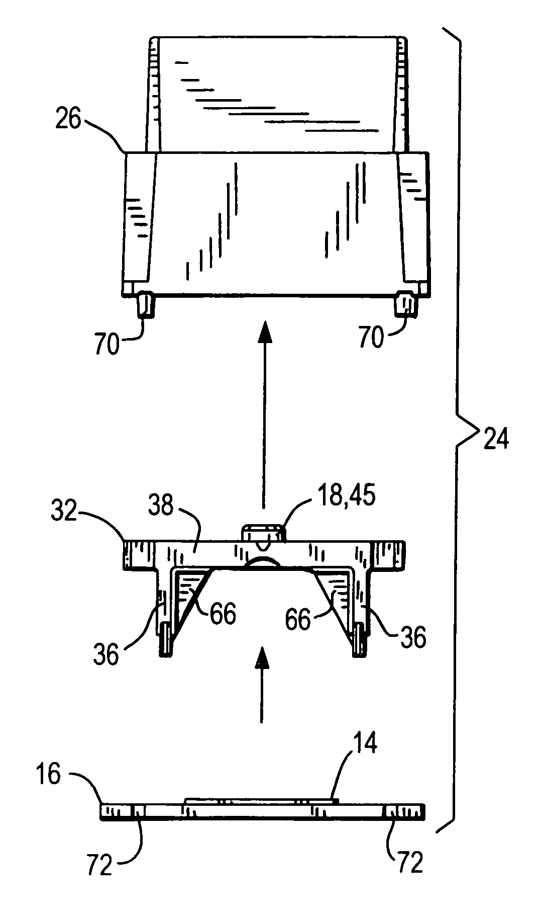
[0022]As shown in FIG. 2, the imaging reader 10 includes an imager 14 supported on a printed circuit board 16 and a focusing collection lens 18 in front of the imager. The imager 14 is a solid-state device, for example, a CCD or a CMOS device and preferably has a linear array of addressable image sensors operative for sensing light passing through the window 12...


PUM


Abstract

An assembly for collecting light from indicia includes a chassis having a port through which the light from the indicia passes, and walls bounding an interior compartment. A self-retaining frame constituted of an optical material is non-adhesively mounted within the compartment in an assembled position. The frame has an integral lens optically aligned with the port in the assembled position for optically modifying the light passing through the port, and a plurality of legs in gripping frictional interference engagement with the walls in the assembled position. A sensor is optically aligned with the lens, for sensing the light optically modified by the lens.

Description

BACKGROUND OF THE INVENTION[0001]Various electro-optical readers have previously been developed for reading both one- and two-dimensional bar code symbols appearing on a label, or on a surface of a target. The bar code symbol itself is a coded pattern of indicia. Generally, the readers electro-optically transform graphic indicia of the symbols into electrical signals, which are decoded into alphanumeric characters. The resulting characters describe the target and / or some characteristic of the target with which the symbol is associated. Such characters typically comprise input data to a data processing system for applications in point-of-sale processing, inventory control, article tracking and the like.[0002]Moving beam electro-optical readers have been disclosed, for example, in U.S. Pat. No. 4,251,798; No. 4,369,361; No. 4,387,297; No. 4,409,470; No. 4,760,248; and No. 4,896,026. Typically, a laser beam is directed toward a one- or two-dimensional coded symbol. The laser beam is re...

Claims


Application Information

Patent Timeline
Patent Type & Authority Patents(United States)
IPC IPC(8): G06K7/10
CPCG02B7/022G06K7/10831
Inventor WITTENBERG, CARLVINOGRADOV, IGORDRZYMALA, MARK
Owner SYMBOL TECH LLC
Why Eureka
Try Eureka