Sprayer for a gardening purpose

a technology for gardening and spraying, applied in the field of spraying, can solve the problems of easy deviation of the piston rod and the crank of the pumping device from the central position during a long-term use, and the danger of touching the liquid that many users are toxic, and achieve the effect of enhancing the strength of the sprayer

Inactive Publication Date: 2010-12-21
SK & Y AGRI EQUIP
View PDF12 Cites 34 Cited by
  • Summary
  • Abstract
  • Description
  • Claims
  • Application Information

AI Technical Summary

Benefits of technology

[0006]The primary objective of the present invention is to provide a sprayer, wherein the container is provided with a plurality of fixing plates secured in the fixing brackets of the base so that the container is combined with the base solidly and stably to enhance the strength of the sprayer.
[0007]Another objective of the present invention is to provide a sprayer, wherein the piston rod of the pumping device is encompassed and protected by the barrel, and the crank of the pumping device is encompassed between and protected by the two guard brackets, so that the piston rod and the crank of the pumping device are operated exactly and stably without deviating from the central position.
[0009]A further objective of the present invention is to provide a sprayer, wherein the user can control the control knob of the control handle to release and decrease the pressure in the pressure chamber of the pressure tank automatically without having to touch the liquid that many be toxic, thereby protecting the user's safety.

Problems solved by technology

However, the container is not combined with the base solidly and stably, thereby decreasing the strength of the sprayer.
In addition, the piston rod and the crank of the pumping device are moved and operated frequently, so that the piston rod and the crank of the pumping device easily deviate from the central position during a long-term utilization.
Further, the drive handle is mounted on the right side of the drive shaft so that the drive handle is only available for right-handed users.
Further, the pressure release valve is mounted in the container that contains liquid so that a user's hand has to extend into the container to operate the pressure release valve, thereby causing danger to the user when touching the liquid that many be toxic.

Method used


Image

  • Sprayer for a gardening purpose
  • Sprayer for a gardening purpose
  • Sprayer for a gardening purpose

Examples


Embodiment Construction

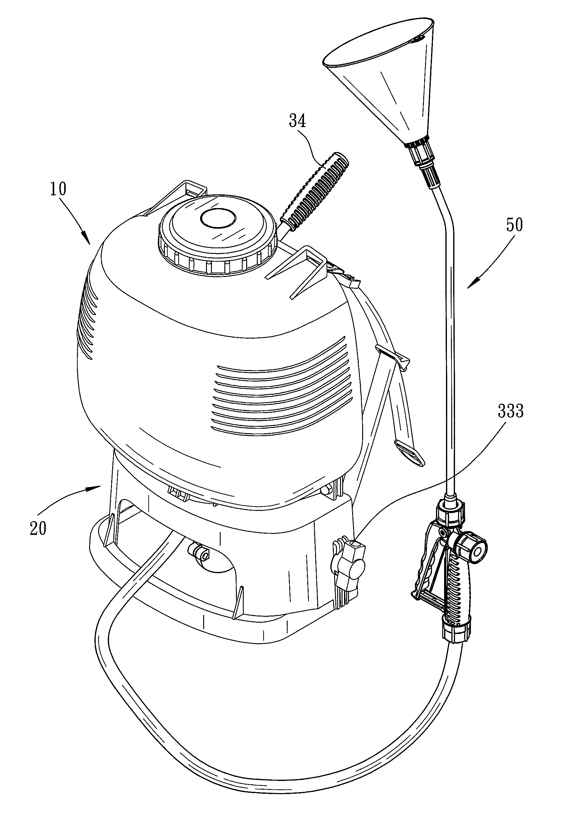
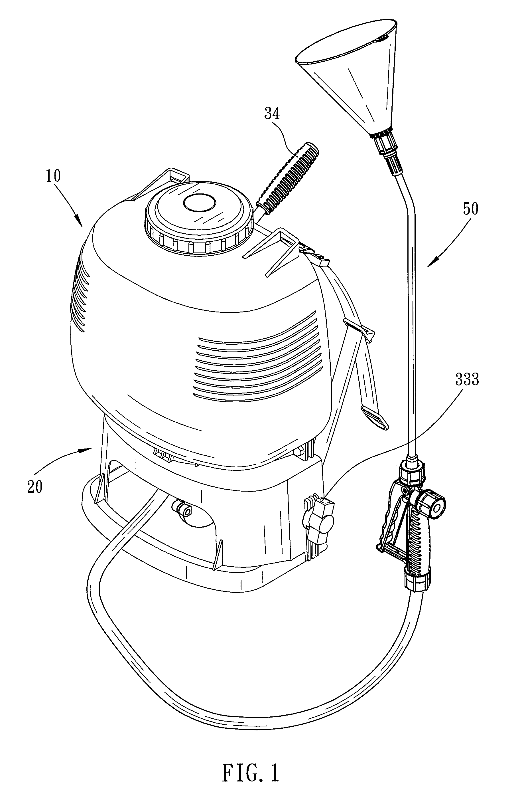
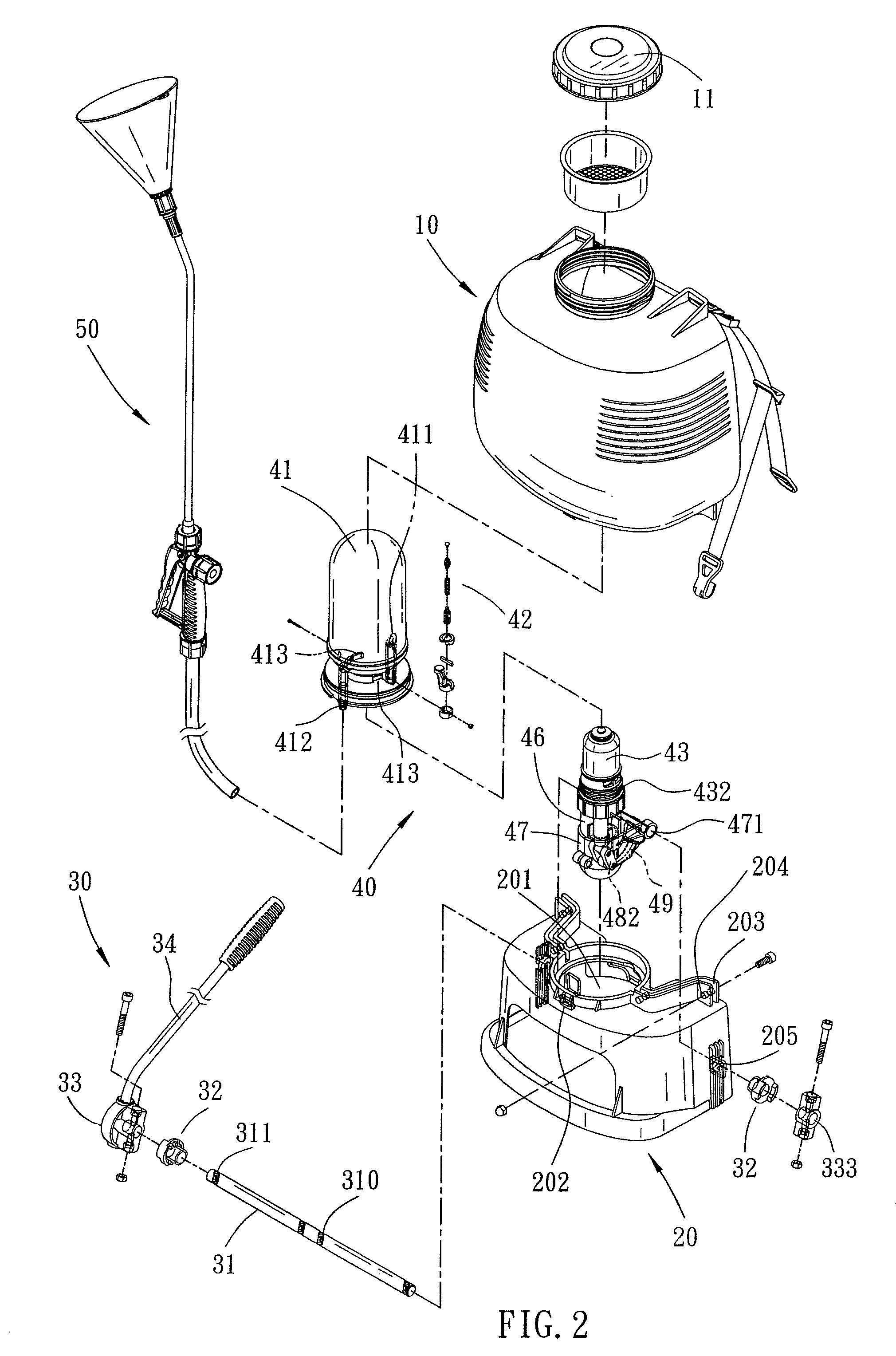
[0024]Referring to the drawings and initially to FIGS. 1-12, a sprayer in accordance with the preferred embodiment of the present invention comprises a base 20, a container 10, a drive device 30, a pumping device 40, and an outlet pipe 50.

[0025]The base 20 has an open top provided with a protruding hollow mounting portion 201 and a plurality of recessed fixing brackets 203. Each of the fixing brackets 203 of the base 20 is located outside of the mounting portion 201 and is provided with a plurality of fixing holes 204. The mounting portion 201 of the base 20 has a periphery provided with a locking groove 202. The base 20 has a side provided with a substantially T-shaped guiding groove 206 (see FIG. 6) and has two opposite ends each provided with a shaft hole 205.

[0026]The container 10 is mounted on the base 20 and has an open bottom provided with a protruding hollow mounting section 101 mounted in the mounting portion 201 of the base 20 and a plurality of fixing plates 103 secured i...


PUM


Abstract

A sprayer includes a base, a container, a drive device, a pumping device, and an outlet pipe. The drive device includes a drive shaft and a drive handle. The pumping device includes a pressure tank, a pressure release valve, a piston cylinder, a barrel, a piston, a piston rod, two guard brackets and a crank. The container is provided with a plurality of fixing plates secured in the fixing brackets of the base so that the container is combined with the base solidly and stably to enhance the strength of the sprayer. The piston rod is encompassed and protected by the barrel, and the crank is encompassed between and protected by the two guard brackets, so that the piston rod and the crank are operated exactly and stably.

Description

BACKGROUND OF THE INVENTION[0001]1. Field of the Invention[0002]The present invention relates to a sprayer (or an atomizer) and, more particularly, to a sprayer that sprays liquid outwardly for a gardening purpose.[0003]2. Description of the Related Art[0004]A conventional sprayer comprises a base, a container, a drive device, a pumping device, and an outlet pipe. The drive device includes a drive shaft and a drive handle. The pumping device includes a pressure tank, a pressure release valve, a piston cylinder, a piston, a piston rod and a crank. However, the container is not combined with the base solidly and stably, thereby decreasing the strength of the sprayer. In addition, the piston rod and the crank of the pumping device are moved and operated frequently, so that the piston rod and the crank of the pumping device easily deviate from the central position during a long-term utilization. Further, the drive handle is mounted on the right side of the drive shaft so that the drive ...

Claims


Application Information

Patent Timeline
Patent Type & Authority Patents(United States)
IPC IPC(8): B05B9/08B05B9/04
CPCB05B9/0877A01C23/008A01G25/09A01M7/0046A01M7/00A01M7/0017
Inventor WU, JUI-CHANG
Owner SK & Y AGRI EQUIP
Why Eureka
Try Eureka