Load transmission body for vehicle

a transmission body and vehicle technology, applied in the direction of roofs, transportation and packaging, passenger space, etc., can solve the problems of increasing production costs, difficult to exhibit a sufficient effect in vehicles, and difficult to receive the input load from the seat in sufficient quantities, so as to achieve efficient transmission of input load

Inactive Publication Date: 2010-12-21
HONDA MOTOR CO LTD
View PDF28 Cites 17 Cited by
  • Summary
  • Abstract
  • Description
  • Claims
  • Application Information

AI Technical Summary

Benefits of technology

[0014]Therefore, the invention was conceived in view of the above-described circumstances and provides a load transmission body for a vehicle, the load transmission body being capable of efficiently transmitting an input load from a seat to the floor of the vehicle body while suppressing an increase in thickness of the constituent members.
[0028]According to the invention, since it is possible to transmit an impact load that has been imparted from the seat to the side wall to the front reinforcing wall and the rear reinforcing wall via the side reinforcing member that reinforces the side wall, it is possible to efficiently transmit an input load from a seat to the floor of the vehicle body without causing an increase in thickness of the constituent members.

Problems solved by technology

There is a problem in that it easily becomes a cause of an increase in production cost or weight
Moreover, in the load structure that attaches a reinforcing member that extends in the vehicle width direction at the lower end of the inner side of the console box (Japanese Unexamined Patent Application, First Publication No. 2005-335523), there is a problem in that it is difficult to exhibit a sufficient effect in vehicles in which the load input portion from the seat is set at a high position.
Moreover, in the load structure in which the left-side wall and right-side wall of a console box are coupled by beam-shaped reinforcing members that extend in the vehicle width direction (U.S. Pat. No. 5,897,155), there is are problems in that the load input position from the seat and the installation position of the reinforcing members are shifted each other depending on the adjustment position in the front-back direction of the seat, and it is difficult to sufficiently receive the input load from the seat.

Method used


Image

  • Load transmission body for vehicle
  • Load transmission body for vehicle
  • Load transmission body for vehicle

Examples


Embodiment Construction

[0038]Hereinafter, an embodiment in accordance with the invention will be described with reference to the appended drawings.

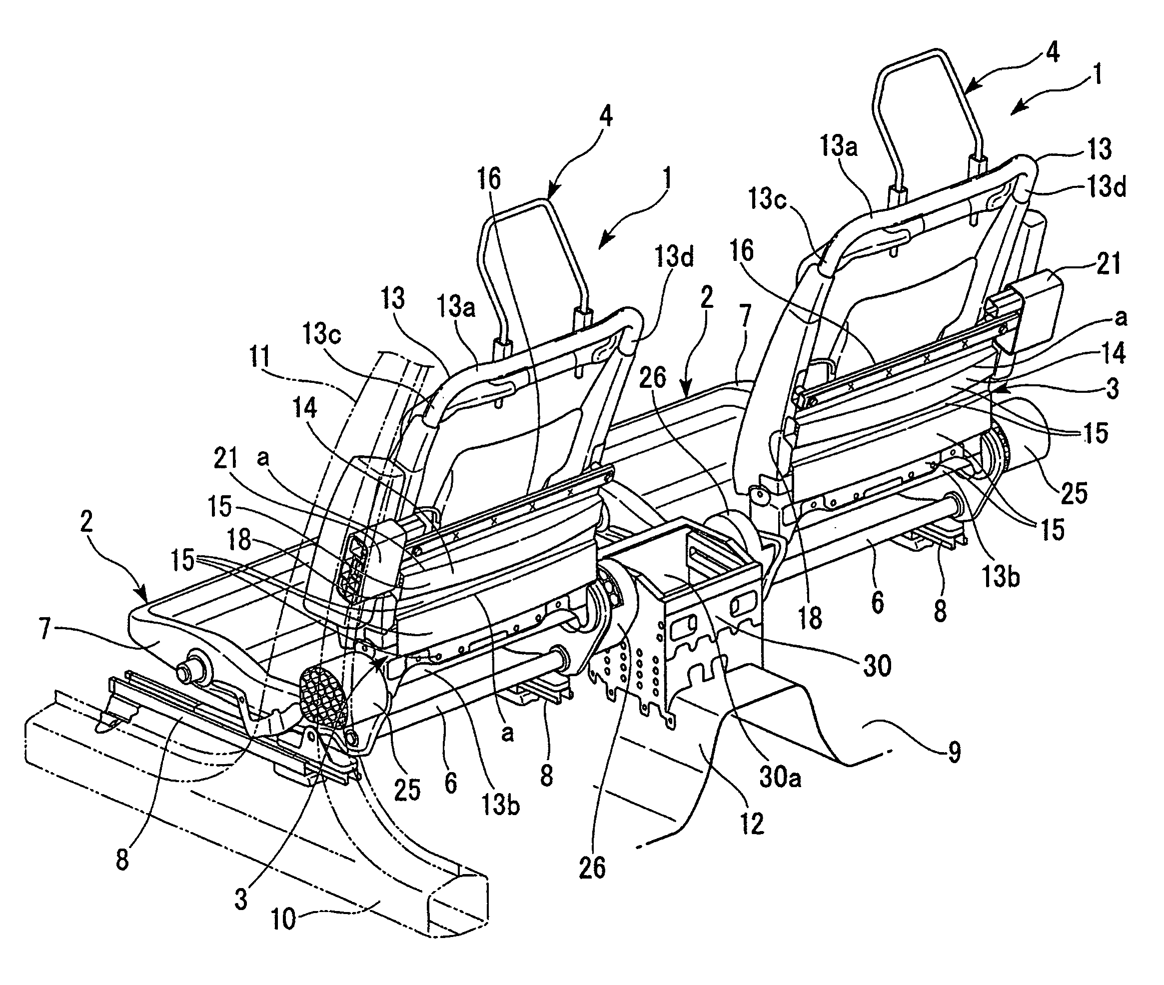
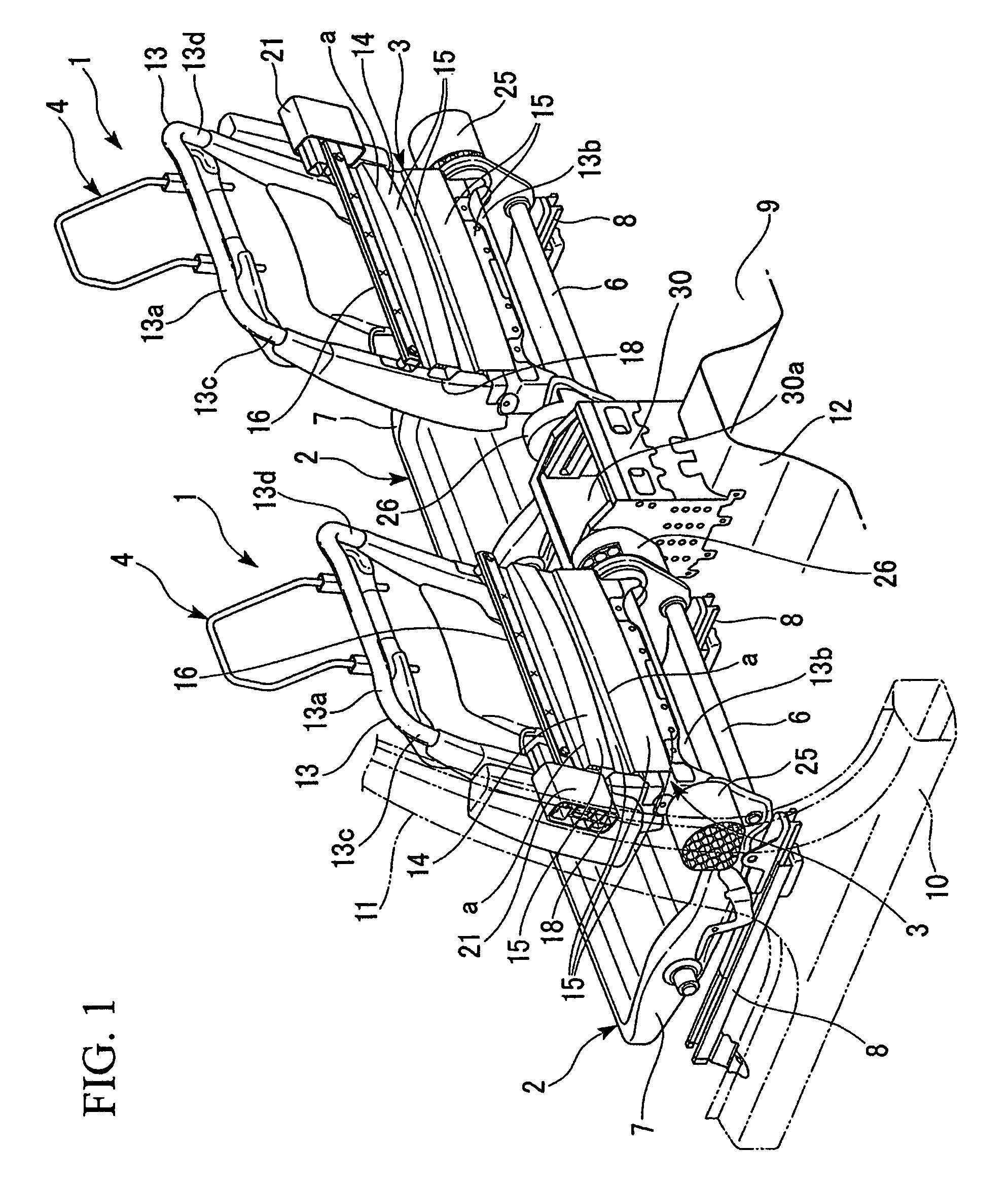
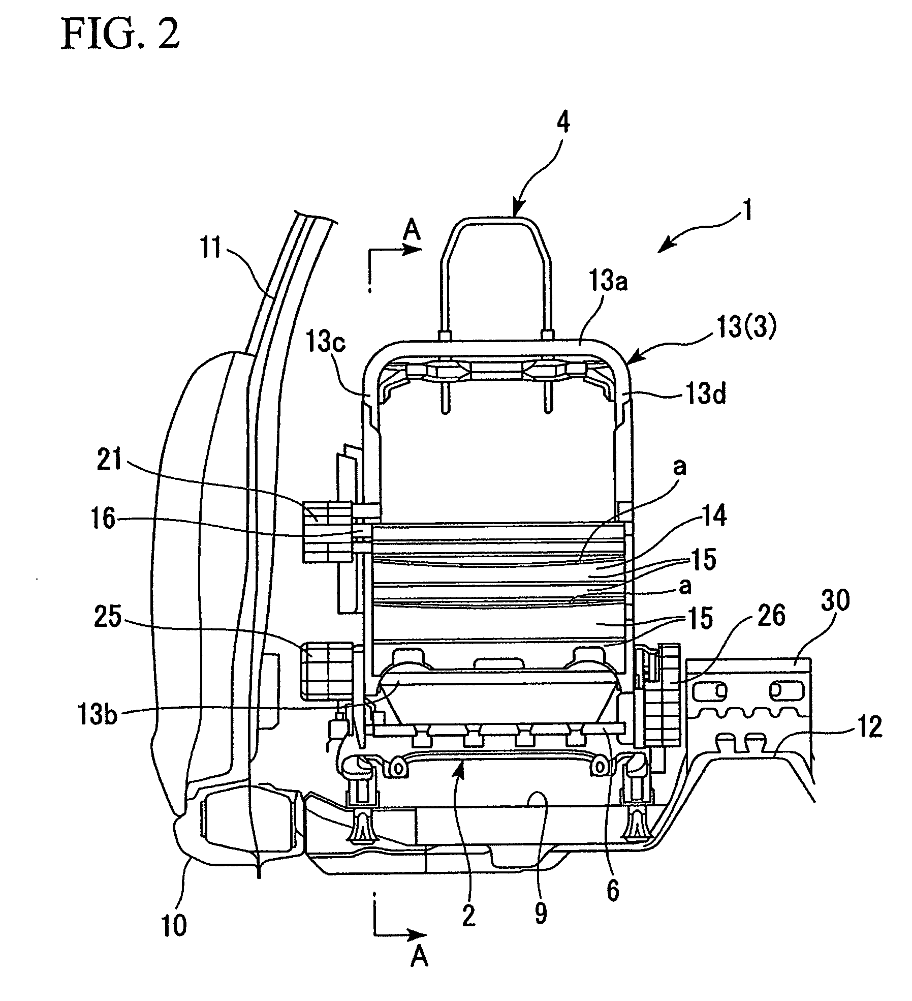
[0039]FIG. 1 is a perspective view of the cabin interior of a vehicle as seen from the rear side of a vehicle seat 1 on the front seat side, and FIG. 2 is a rear view of the vehicle seat 1.

[0040]In FIGS. 1 and 2, only the frame members of the vehicle seat 1 are shown.

[0041]The vehicle seat 1 includes a seat cushion 2, a seat back 3, and a headrest 4. The seat cushion 2 supports an occupant's buttocks. The seat back 3 is connected with the rear end portion of the seat cushion 2, and supports the lumbar and chest (back) of an occupant. The headrest 4 is supported by the upper portion of the seat back 3, and supports the head and neck of an occupant.

[0042]The seat cushion 2 includes a cushion frame 7 to which a rear cross member 6 that extends along the vehicle width direction is attached at the rear end portion. The cushion frame 7 is attached to a vehicle body f...


PUM


Abstract

A load transmission body for a vehicle, transmitting an impact load to a floor of the vehicle body, the load transmission body includes: a pair of side walls fixed to the floor of the vehicle body and extending in a vehicle front-back direction; a front reinforcing wall having a closed cross-sectional structure, extending in a vehicle width direction, and reciprocally coupling with the pair of side walls; a rear reinforcing wall disposed at a vehicle rear side of the front reinforcing wall, having a closed cross-sectional structure, extending in the vehicle width direction, and reciprocally coupling with the pair of side walls; and a side reinforcing member disposed at each of the front reinforcing wall and the rear reinforcing wall, extending in the vehicle front-back direction, and coupling the front reinforcing wall with the rear reinforcing wall.

Description

BACKGROUND OF THE INVENTION[0001]1. Field of the Invention[0002]The present invention relates to a load transmission body for a vehicle that transmits an impact load that has been imparted from the side of a vehicle body to a seat on which an occupant sits to the floor of the vehicle body.[0003]This application claims priority from Japanese Patent Application No. 2008-181438, filed on Jul. 11, 2008, the contents of which are incorporated herein by reference.[0004]2. Description of Related Art[0005]A vehicle structure is known that transmits an impact load that has been imparted to the side portion of a vehicle to a floor tunnel at the middle of the vehicle in the vehicle width direction via a seat.[0006]Also, as a load transmission body that transmits a lateral load from the seat to the floor tunnel, there is known a load transmission body that utilizes the console box that is adjacently disposed on the inner side of the seat in the vehicle width direction.[0007]Such a load transmis...

Claims


Application Information

Patent Timeline
Patent Type & Authority Patents(United States)
IPC IPC(8): B60J7/00
CPCB60N2/4235B60R7/04B62D21/157B62D25/2036
Inventor YAMAKI, JOGENABE, TAKESHIOKU, HISATO
Owner HONDA MOTOR CO LTD
Why Eureka
Try Eureka