Intelligent track system for mounting electronic equipment

a track system and intelligent technology, applied in the direction of burglar alarm mechanical actuation, furniture parts, instruments, etc., can solve the problems of not providing actual and direct feedback to the software program, equipment generates heat and consumes power, and managers have a significant burden in tracking and managing available spaces

Inactive Publication Date: 2010-12-28
LIEBERT
View PDF67 Cites 74 Cited by
  • Summary
  • Abstract
  • Description
  • Claims
  • Application Information

AI Technical Summary

Problems solved by technology

This equipment generates heat and consumes power.
For medium to large complexes, IT managers have a significant burden in tracking and managing available spaces on the racks for mounting electronic equipment.
However, it is understood that the system does not provide actual and direct feedback to the software program and thus can only provide such information based on the operator input.
If the data is incorrectly entered, so that equipment is actually in a different location, then the software predictive capabilities are based on error and are potentially harmful by providing misleading information.
It is not uncommon for electronic equipment to be assigned to a given location in a rack, but the operator is unable to install the equipment in that location because a previous operator installed an earlier piece of electrical equipment in that location.
The technician then installs the new equipment in yet a different location than intended and the data is not updated in the records, thus perpetuating the problem.
Additionally, it is not uncommon for equipment to migrate from location to location or rack to rack as the IT computing environment is chaotic and ever changing.
Thus, tracking these changes is difficult, labor-intensive, and time consuming.

Method used


Image

  • Intelligent track system for mounting electronic equipment
  • Intelligent track system for mounting electronic equipment
  • Intelligent track system for mounting electronic equipment

Examples


Embodiment Construction

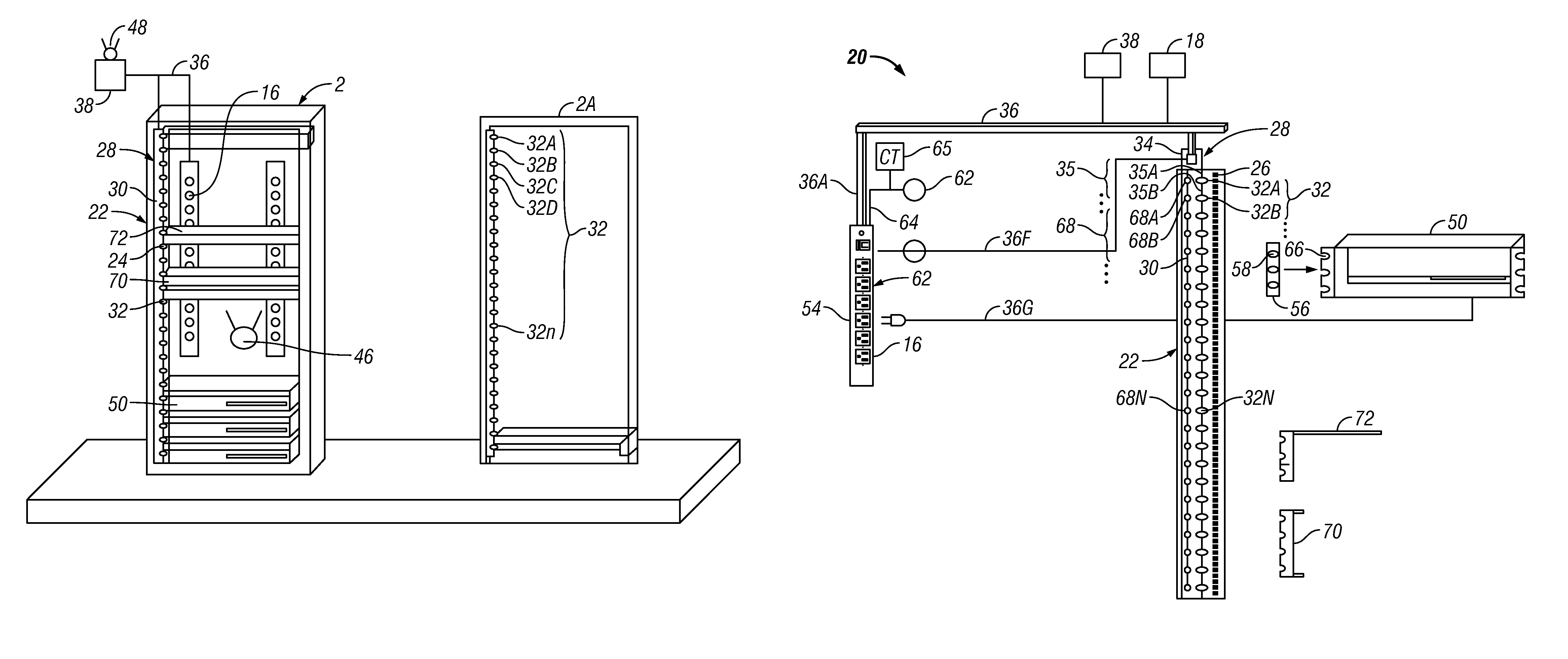
[0019]Applicants have created an intelligent mounting track system that can sense the “U” spaces used by electrical equipment, such as on a rack in an electrical cabinet, and provide such information to a remote location. The information can be communicated to an electronic processor with software to interpret the information and indicate space utilization to assist information technology (“IT”) managers and other decision-makers in determining more accurately available locations for additional equipment from remote locations without physical inspection.

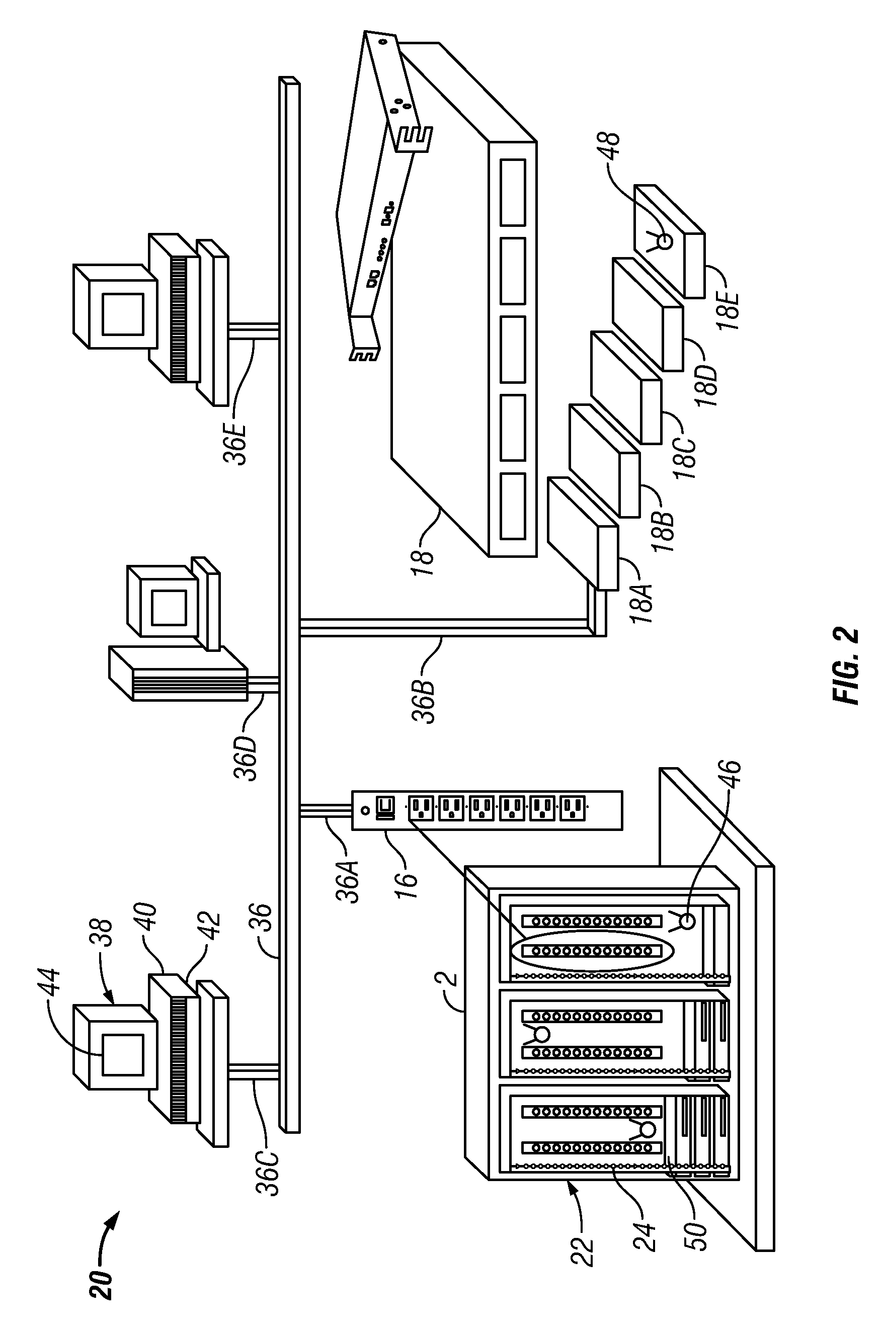
[0020]FIG. 2 is a schematic diagram of an exemplary system having an intelligent track system. The system 20 includes a rack with mounting spaces for mounting electronic devices, one or more sensors for sensing at least the presence of an electronic device, a communications link coupled to the sensor, and an electronic processor coupled to the communications link to receive information on the status of the sensor and the current loca...


PUM


Abstract

The present invention provides an intelligent track system generally mounted in a network, server, or telecom rack / enclosure rack rail that can sense the spaces, such as “U” spaces, used by electronic equipment, shelving, or blanking panels and provide such information to a remote location. Information technology (IT) managers and other decision-makers can remotely view the actual available spaces and determine appropriate locations for installing additional equipment. Criteria can be based on actual available space and for some embodiments in conjunction with predictive or actual sensed temperatures proximate to the spaces, available cooling capacity, power loads, and available power capacity. In at least one embodiment, the intelligent mounting track system can include a plurality of sensors mounted along the rack surfaces that collectively or individually uniquely identify which spaces are occupied. The information can be communicated to an electronic processor with software to interpret the data and indicate space utilization.

Description

CROSS REFERENCE TO RELATED APPLICATIONS[0001]This application claims the benefit of U.S. Provisional Application Ser. No. 60 / 914,119, filed Apr. 26, 2007, which is incorporated herein by reference.STATEMENT REGARDING FEDERALLY SPONSORED RESEARCH OR DEVELOPMENT[0002]Not applicable.REFERENCE TO APPENDIX[0003]Not applicable.BACKGROUND OF THE INVENTION[0004]1. Field of the Invention[0005]The present invention relates generally to electronic equipment cabinets and racks, and more particularly to racks having multiple mounting locations for the equipment.[0006]2. Description of the Related Art[0007]With the expansion of telecommunication and computer technology, increasing amounts of electronic equipment are required at businesses and other facilities. Typically, the equipment is coupled to racks as shown in FIG. 1. The equipment is generally organized in a cabinet 2 of standard dimensions with multiple vertical racks 4 to support columns of equipment. A plurality of standardized preset s...

Claims


Application Information

Patent Timeline
Patent Type & Authority Patents(United States)
IPC IPC(8): G06K15/00
CPCG06F1/181G06F1/183H05K7/1498
Inventor SALIARIS, DAVID G.
Owner LIEBERT
Why Eureka
Try Eureka