Miniaturized linear light source sub-module for various format main modules

a technology of linear light source and sub-module, which is applied in the field of optics, can solve the problems of reducing and reducing the efficiency and intensity of light source, so as to maximize light reflection and enhance the uniformity of emitted light. , the effect of high efficiency

Active Publication Date: 2010-12-28
PIXON TECH CORP
View PDF9 Cites 23 Cited by
  • Summary
  • Abstract
  • Description
  • Claims
  • Application Information

AI Technical Summary

Benefits of technology

[0014]To achieve these and other advantages and in order to overcome the disadvantages of the conventional method in accordance with the purpose of the invention as embodied and broadly described herein, the present invention provides a miniaturized linear light source sub-module comprising a highly efficient light guide with a first reflecting surface to maximize light reflection and a second reflecting surface to enhance the uniformity of the emitted light, at least one light emitting diode light source, an array of lenses for high-resolution imaging of a surface, and a sub-module housing.
[0015]The highly efficient light guide of the miniaturized linear light source sub-module maximizes light reflection, prevents light loss at the entry point, and provides a uniform emitted light.

Problems solved by technology

However, since the end of the transparent light rod 120 is flat, much of the light is reflected back and is lost.
This lowers the efficiency and intensity of the light source.
Unfortunately, some of the light exits the transparent light rod 120 in directions not intended.
This results in an additional loss of light.
This increases the cost of the light source.
As a result the conventional light source's emitted light is not uniform.
However, this type of lens is expensive to manufacture.
In addition, a major disadvantage of this type of lens is that because of the number of lenses and the difficulty in orienting them, it is not practical to shape the ends of the lenses so that they can magnify the surface that they are imaging; flat ends are used.
In order to increase the imaging resolution, it is necessary to use larger numbers of smaller-diameter rod lenses 131, limiting the maximum resolution and driving up the costs as the desired resolution increases.
Furthermore, suppliers for the necessary GRIN fiber optic strands are limited, and thus the base materials themselves are expensive.
Additional, the glass used in the conventional rod lens contains lead which is not environmentally friendly.

Method used


Image

  • Miniaturized linear light source sub-module for various format main modules
  • Miniaturized linear light source sub-module for various format main modules
  • Miniaturized linear light source sub-module for various format main modules

Examples


Embodiment Construction

[0062]Reference will now be made in detail to the preferred embodiments of the present invention, examples of which are illustrated in the accompanying drawings. Wherever possible, the same reference numbers are used in the drawings and the description to refer to the same or like parts.

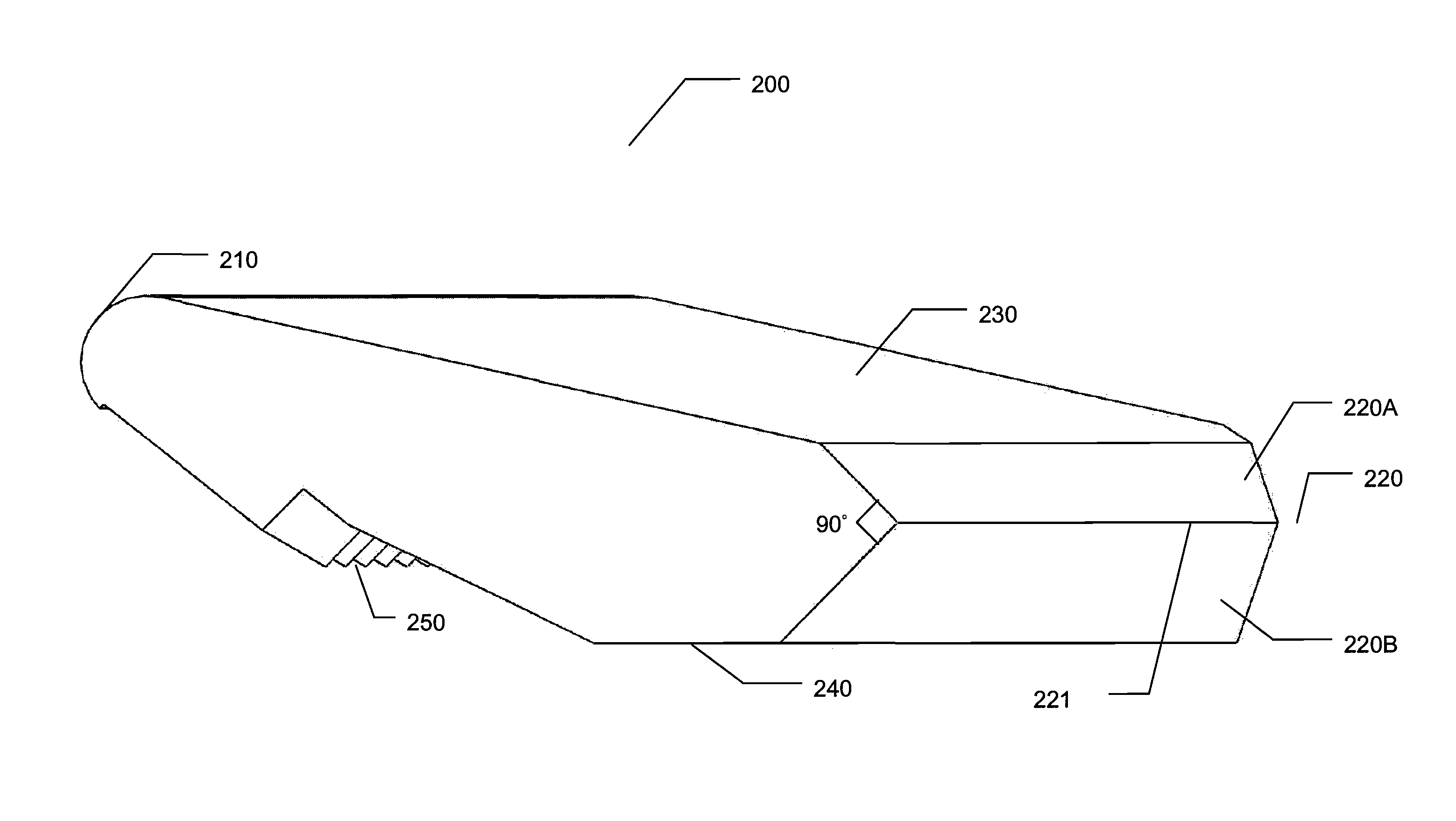
[0063]Refer to FIG. 2, which is a three dimensional drawing illustrating a light guide with an asymmetrical saw-toothed light reflecting surface according to an embodiment of the present invention, to FIG. 3, which is a perspective view of a light guide with a circular light emitting surface according to an embodiment of the present invention, and to FIG. 4, which is a perspective view of a light guide with a polygonal light emitting surface according to an embodiment of the present invention.

[0064]The light guide 200 of the present invention comprises a light emitting surface 210, a v-shaped light reflecting surface 220, an asymmetrical saw-toothed light reflecting surface 250, a bottom surface 240,...


PUM


Abstract

A miniaturized linear light source sub-module comprising a symmetrical lens array, a light guide bar with dual reflecting surfaces, at least one light emitting diode light source, and a sub-module housing is disclosed. The symmetrical lens array comprises two identical covers, two identical lens sections, and a middle holder. Each lens section comprises a plurality of lenses disposed on the top and bottom of the lens section. The dual reflecting surface light guide comprises a light emitting surface, a v-shaped light reflecting surface, an asymmetrical saw-toothed light reflecting surface, an apex cut-off surface, and a bottom cut-off surface. At least one light emitting diode light source is connected to an end of the dual reflecting surface light guide. The sub-module housing holds the lens array assembly, the dual reflecting surface light guide, and the at least one light emitting diode light source to form the miniaturized linear light source sub-module.

Description

BACKGROUND OF THE INVENTION[0001]1. Field of the Invention[0002]The present invention relates to optics. More specifically, the present invention discloses a miniaturized linear light source sub-module comprising a highly efficient light guide with a first reflecting surface to maximize light reflection and a second reflecting surface to enhance the uniformity of the emitted light, at least one light emitting diode light source, an array of lenses for high-resolution imaging of a surface, and a sub-module housing.[0003]2. Description of the Prior Art[0004]Linear light sources emit light in a different direction from the direction the light originated from. For example, a light is produced by a light emitting diode at an angle of zero degrees. By affecting the direction of the light beam the linear light source can emit the light at various angles such as 90 degrees.[0005]Refer to FIG. 1A, which is a drawing illustrating a light source of the prior art. As shown in FIG. 1A, the conve...

Claims


Application Information

Patent Timeline
Patent Type & Authority Patents(United States)
IPC IPC(8): F21V7/07
CPCG02B6/0035H04N1/02815H04N1/02835H04N1/02885
Inventor WU, RONG-YAWCHEN, SHIH-CHECHEN, YEN-CHIEHYEN, CHIH-MINGCHEN, CHING-YI
Owner PIXON TECH CORP
Why Eureka
Try Eureka