Flow control device for improving pressure resistance and hull vibration

a flow control and hull technology, applied in the direction of bilge keels, special-purpose vessels, vessel construction, etc., can solve the problems of increasing hull vibration, not being able to transport large-scale at a time by aircraft, and consuming a lot of fuel, so as to improve the propulsive efficiency of the ship, reduce the vibration caused by the propeller, and save fuel

Active Publication Date: 2010-12-28
SAMSUNG HEAVY IND CO LTD
View PDF5 Cites 0 Cited by
  • Summary
  • Abstract
  • Description
  • Claims
  • Application Information

AI Technical Summary

Benefits of technology

[0025]In accordance with the present invention, vibration caused by the ship propeller can be reduced by only attaching simple fins. Accordingly, a pleasant voyage environment of crews and passengers can be obtained and fuel can be saved through the improvement of propulsive efficiency of the ship.

Problems solved by technology

However, in the case of oil, natural gas, vehicles, and containers with a very large freight volume and a heavy freight weight, they could not be transported in great volumes at a time by the aircraft and, therefore, it is common to transport them by a ship.
However, hull vibration is increased by a ship propeller and a lot of fuel is consumed due to an increase of an engine horsepower resulting from the large ship moving at a high speed.
It can also be seen that propulsive efficiency of the ship is not much improved since pressure resistance is not reduced as described above.

Method used


Image

  • Flow control device for improving pressure resistance and hull vibration
  • Flow control device for improving pressure resistance and hull vibration
  • Flow control device for improving pressure resistance and hull vibration

Examples


Embodiment Construction

[0037]Hereinafter, an embodiment of the present invention will be described in detail with reference to the accompanying drawings.

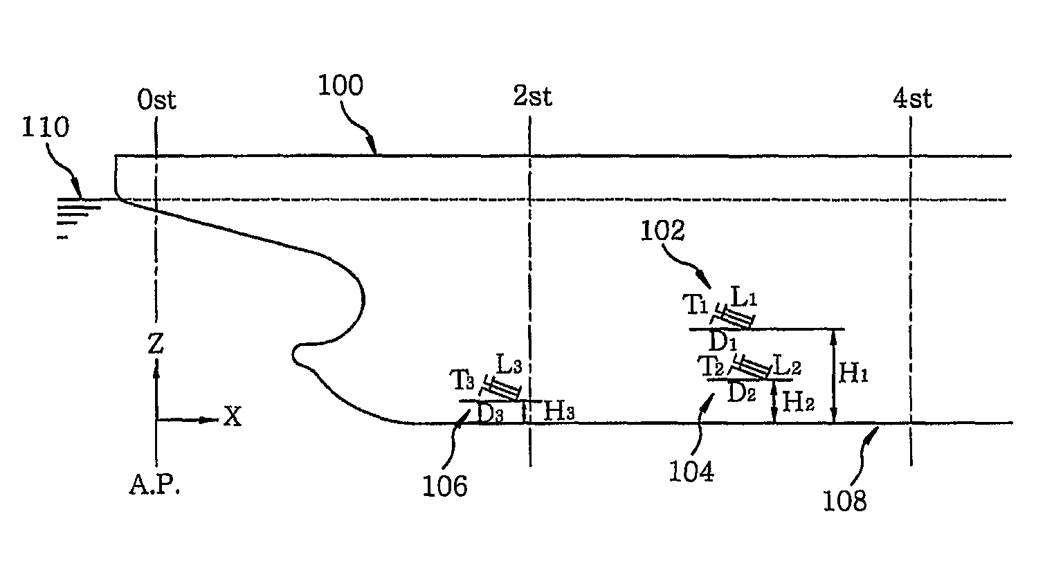
[0038]FIG. 5 is a schematic side view of a ship provided with a flow control mechanism for improving pressure resistance and hull vibration in accordance with an embodiment of the present invention; and FIGS. 6A to 6C are partial plan views of the ship provided with the flow control mechanism shown in FIG. 5.

[0039]In the present embodiment, an upper fin 102 is located between a second station and a fourth station in the length direction (X-axis direction) of a ship 100, and at a height H1 between 30% and 60% of a design draft from the bottom 108 of the ship in the height direction (Z-axis direction) of the ship 100. The upper fin 102 is inclined at an angle D1 of 10 to 30 degrees with respect to a design draught (or base) line.

[0040]A lower fin 104 is located between the second station and the fourth station in the length direction (X-axis direction) of t...


PUM


Abstract

A flow control mechanism, for improving pressure resistance and hull vibration, includes a lower fin and an upper fin. The lower fin is disposed between a second station and a fourth station in a length direction of a ship and between 10% and 20% of a design draft from a bottom of the ship in a height direction of the ship, the lower fin being inclined at an angle of 20 to 40 degrees with respect to a design draught (or base) line. The upper fin is disposed between the second station and the fourth station in the length direction of the ship and between 30% and 60% of the design draft from the bottom of the ship in the height direction of the ship, the upper fin being inclined at an angle of 10 to 30 degrees with respect to the design draught (or base) line. Further, an additional fin is disposed between a first station and a third station in the length direction of the ship and between 5% and 20% of the design draft from the bottom of the ship in the height direction of the ship, the additional fin being inclined at an angle of 10 to 40 degrees with respect to the design draught (or base) line.

Description

TECHNICAL FIELD[0001]The present invention relates to a flow control mechanism for improving pressure resistance and hull vibration, and more particularly, to a flow control mechanism for improving pressure resistance and hull vibration, which is capable of giving a pleasant voyage environment to crews and passengers of a ship by reducing vibration caused by a ship propeller and enhancing propulsive efficiency of the ship.BACKGROUND ART[0002]In the present day, freight has been transported rapidly over the world with the development of transportation means such as aircraft. However, in the case of oil, natural gas, vehicles, and containers with a very large freight volume and a heavy freight weight, they could not be transported in great volumes at a time by the aircraft and, therefore, it is common to transport them by a ship.[0003]In the event that freight is transported by using a ship, it is required to make the ship large and move at high speed in order to transport a great amo...

Claims


Application Information

Patent Timeline
Patent Type & Authority Patents(United States)
IPC IPC(8): B63H1/18
CPCB63B39/005B63H5/16B63B3/44B63B39/06B63B1/32
Inventor HONG, CHUN BEOMBAE, JOON HWANKIM, KI HYUNAHN, SUNG MOKHWANGBO, SEUNG MYUN
Owner SAMSUNG HEAVY IND CO LTD
Why Eureka
Try Eureka