Transmission line system having high common mode impedance

a transmission line and high common mode technology, applied in the field of electronic devices, can solve the problems of complex and functional systems, adverse effects on differential and common mode impedance of transmission lines, and undesirable side effects of systems having three or more transmission lines, so as to reduce the size and cost of the system, improve the performance of the system, and add flexibility in packaging and application.

Active Publication Date: 2010-12-28
QUALCOMM INC
View PDF24 Cites 35 Cited by
  • Summary
  • Abstract
  • Description
  • Claims
  • Application Information

AI Technical Summary

Benefits of technology

[0009]The various aspects of the present invention can operate without the need for supplemental ground or power strips, improving the performance of the system and adding flexibility in packaging and application while reducing the size and cost of the system. Further aspects, features and advantages of the present invention are described in detail below with reference to the following Figures.

Problems solved by technology

However, with the increase in complexity and functionality of many devices, such as mobile phones, computers, personal digital assistants, personal navigation systems and the like, there is an increased need for a transmission line system that can handle differential signals in a multiplexed fashion.
Unfortunately, systems having three or more transmission lines have a number of undesirable side effects, including adverse effects on the differential and common mode impedances of the transmission lines.
Unfortunately, it is often the case that the presence of additional ground or power strips reduces the common mode impedance of the transmission lines, which is undesirable in a number of applications.
Moreover, the addition of the ground and power strips increases the complexity, cost, and size of the package and restricts the environments in which it can be used.

Method used


Image

  • Transmission line system having high common mode impedance
  • Transmission line system having high common mode impedance
  • Transmission line system having high common mode impedance

Examples


Embodiment Construction

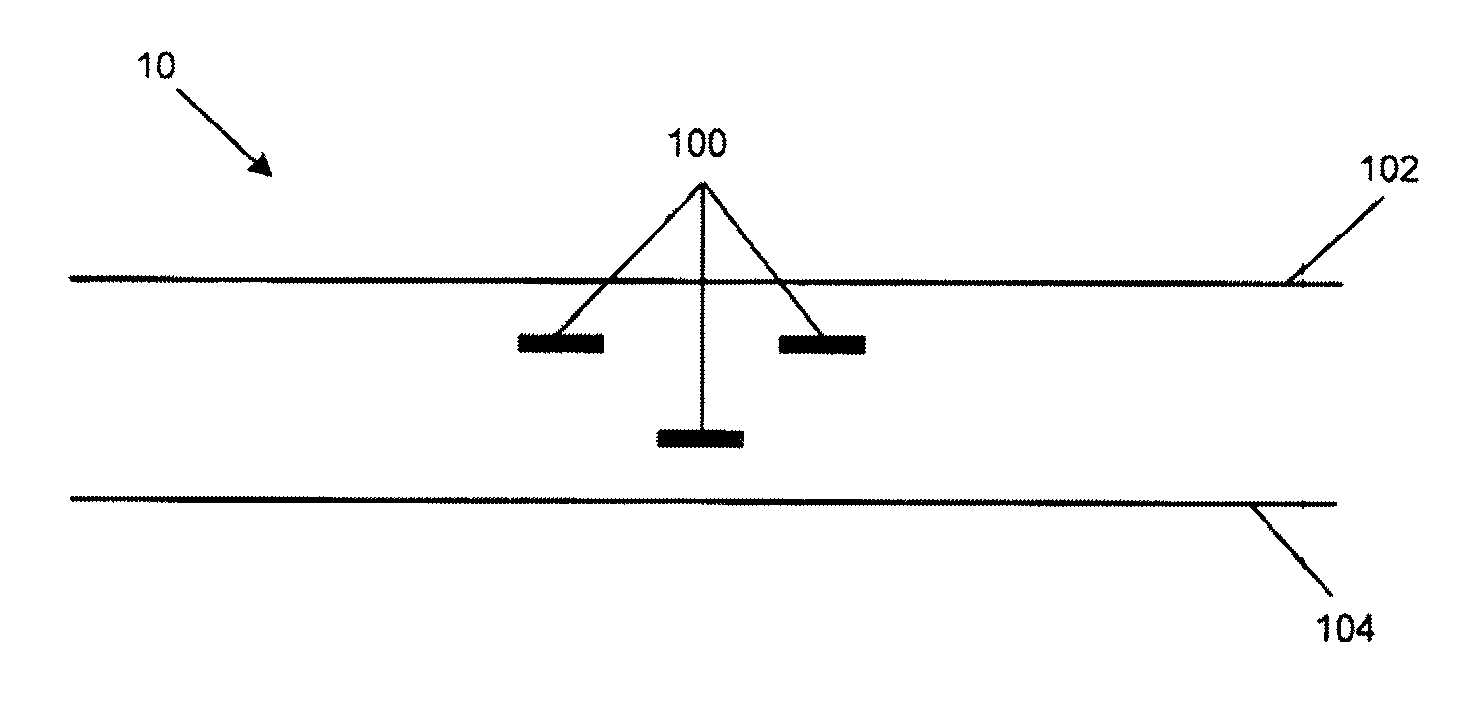
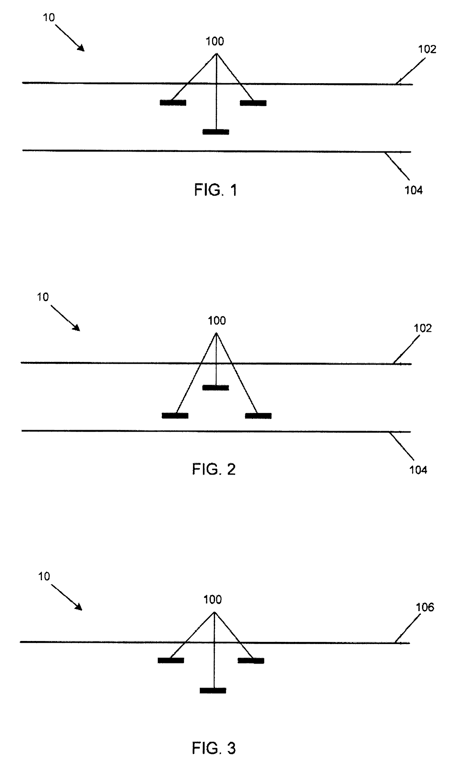
[0023]The present invention is described herein with reference to its preferred aspects and selected variations thereof. As the following detailed description is both enabling and exemplary in nature, it should not be construed as limiting the scope of the following claims. The present invention, presented in its various aspects, generally includes three coupled transmission lines disposable on two separate layers of a package, printed circuit board (PCB) or any multilayer stackup in such a way that the differential mode characteristic impedance (Zdiff) is a desired value, such as, for example 100 ohms. The design does not use ground strips between the transmission lines. As a result the common mode characteristic impedance (Zcomm) is higher, which results in higher common mode rejection ratio for the system, and overall improved system performance.

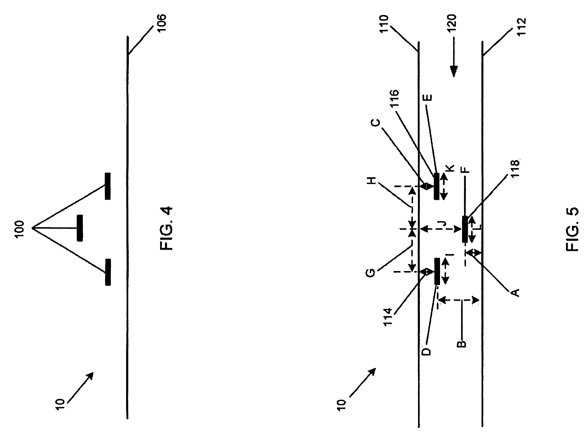
[0024]There are three ways the transmission lines can be paired. Each of these transmission line pairs can transport differential signal...


PUM


Abstract

Systems having three coupled transmission lines designed in such a way that any two of which taken together can be used as a differential transmission line with a roughly equal differential mode characteristic impedance while achieving high level of common mode characteristic impedance. The high level of common mode characteristic impedance is achieved by arrangement of the three transmission lines in distinct planes along a transmission axis.

Description

FIELD OF THE INVENTION[0001]The present invention relates generally to the field of electronics, and more particularly to the field of signal transmission and processing within electronic devices including mobile stations and the like.BACKGROUND[0002]The demand for innovative and specialized portable electronic devices is ever increasing, and accordingly the design, packaging and functionality of electronic devices is constantly adapting and improving to meet the demand. Numerous devices employ two transmission lines for conducting differential signals within the device. However, with the increase in complexity and functionality of many devices, such as mobile phones, computers, personal digital assistants, personal navigation systems and the like, there is an increased need for a transmission line system that can handle differential signals in a multiplexed fashion. Moreover, in an electrical system that uses differential signaling and uses differential transmission lines to transp...

Claims


Application Information

Patent Timeline
Patent Type & Authority Patents(United States)
IPC IPC(8): H01P3/08
CPCH01P3/088H01P5/184H01L2224/16227H01L2924/15311
Inventor PANDEY, SHREE KRISHNA
Owner QUALCOMM INC
Why Eureka
Try Eureka