Methods and systems to predict rotary drill bit walk and to design rotary drill bits and other downhole tools

a technology of rotary drill bit and rotary drill bit, which is applied in the direction of directional drilling, instruments, and wellbore/well accessories, can solve the problems of unfavorable bit walk and particularly excessive bit walk, damage to associated drill string, and inability to explain the right walk of fixed cutter drill bit, etc., to reduce or avoid undesired right walk forces, reduce side forces, and reduce the effect of bha side forces

Active Publication Date: 2010-12-28
HALLIBURTON ENERGY SERVICES INC
View PDF206 Cites 14 Cited by
  • Summary
  • Abstract
  • Description
  • Claims
  • Application Information

AI Technical Summary

Benefits of technology

[0016]Another aspect of the present disclosure may include evaluating various mechanisms associated with “bit walk” in directional wellbores to numerically model directional steering systems, rotary drill bits and / or associated components. Such models have shown that oversized wellbores and / or wellbores with non-circular cross sections may be a major cause of fixed cutter drill bits walking right. Oversized wellbores and / or non-circular wellbores often require large deflection of a rotary drill bit by an associated rotary steering unit to satisfactorily direct the rotary drill bit along a desired trajectory or path to form the directional wellbore. Large deflections may create a side force in the magnitude of thousands of pounds at a contact location point associated with contact between exterior portions of a stabilizer or near bit sleeve. This side force due to BHA deflection may lead to bit walk right. Another right walk force may be generated at the same contact location due to the interaction between near bit stabilizer or near bit sleeve and adjacent portions of the wellbore. To reduce or avoid undesired right walk forces, teachings of the present disclosure may be used to reduce side forces at such contact location. One solution to reduce the BHA side forces may be redesigning the locations of one or more stabilizers along the BHA. Another solution to reduce undesired interaction between a near bit sleeve and / or gage pads with a wellbore may be increasing width of the gage pads, increasing spiral angle of the gage pads, rounding the leading edge of each blade disposed on the sleeve and / or reducing the friction coefficient between exterior portions of the near bit sleeve and the wellbore.

Problems solved by technology

Some prior models used to simulate drilling wellbores often failed to explain why fixed cutter drill bits walk right and may even have very large right walk rates under some specific conditions.
For many downhole drilling conditions, bit walk and particularly excessive amounts of bit walk are not desired.
Excessive amounts of bit walk may also result in damage to an associated drill string and / or “sticking” of the drill string with adjacent portions of a wellbore.
Excessive amounts of bit walk may also result in forming a tortuous wellbore which may create problems while installing an associated casing string or other well completion problems.

Method used


Image

  • Methods and systems to predict rotary drill bit walk and to design rotary drill bits and other downhole tools
  • Methods and systems to predict rotary drill bit walk and to design rotary drill bits and other downhole tools
  • Methods and systems to predict rotary drill bit walk and to design rotary drill bits and other downhole tools

Examples


Embodiment Construction

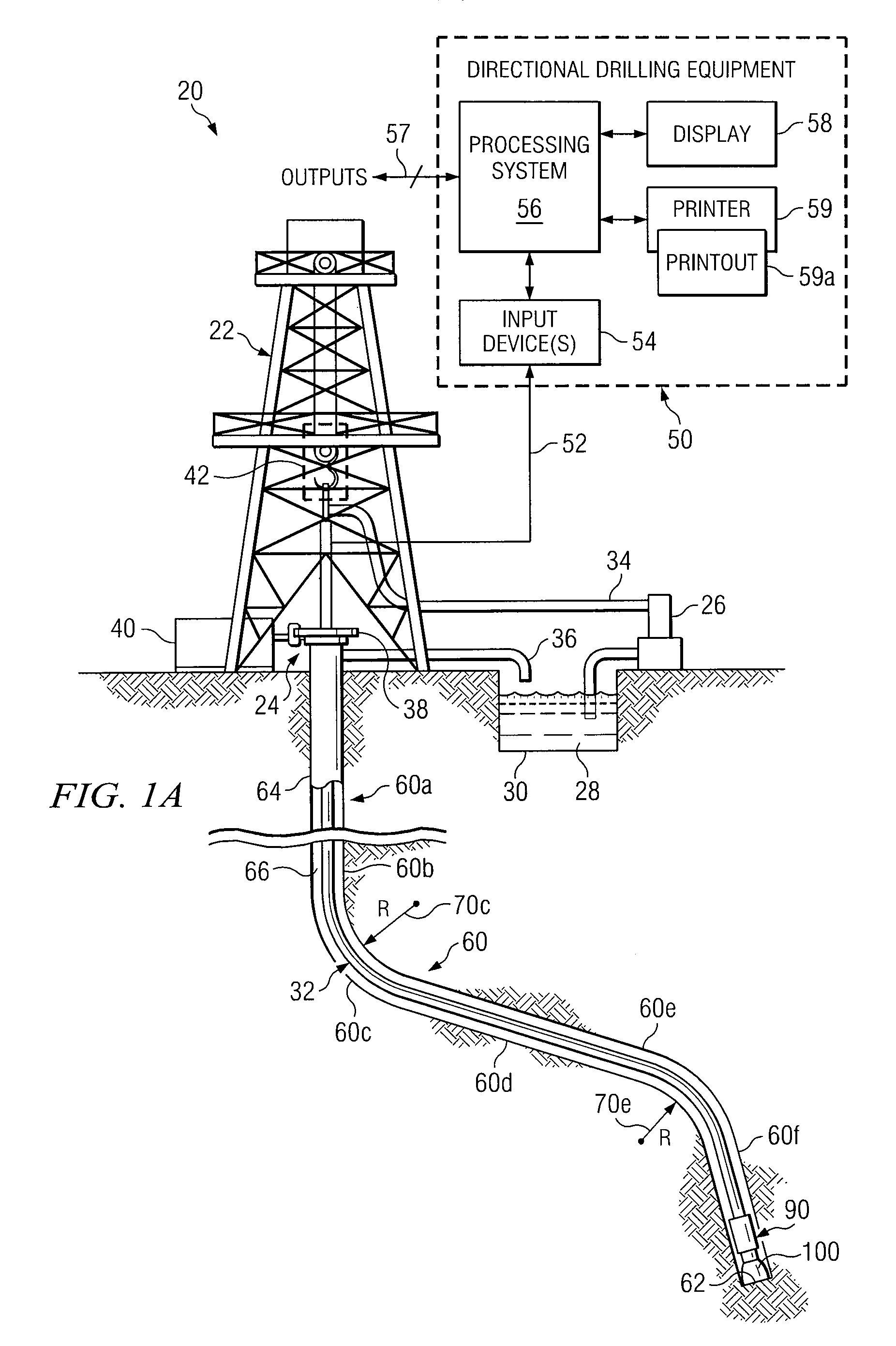
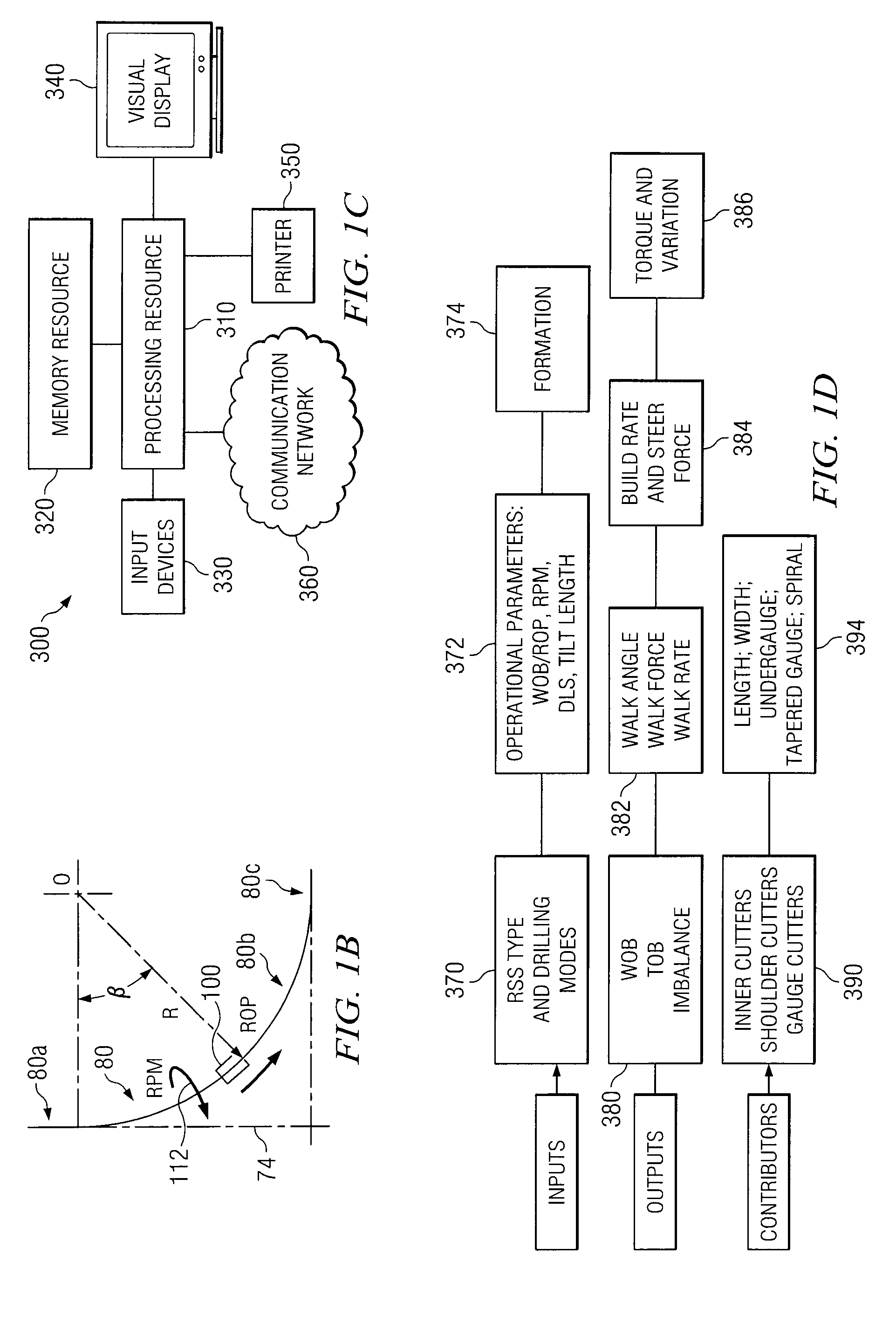
[0072]Preferred embodiments of the invention and its advantages are best understood by reference to FIGS. 1A-18G wherein like number refer to same and like parts.

[0073]The terms “axial taper” or “axially tapered” may be used in this application to describe various components or portions of a rotary drill bit, sleeve, near bit stabilizer, other downhole tool and / or components such as a gage pad disposed at an angle relative to an associated bit rotational axis.

[0074]The term “bottom hole assembly” or “BHA” may be used in this application to describe various components and assemblies disposed proximate a rotary drill bit at the downhole end of a drill string. Examples of components and assemblies (not expressly shown) which may be included in a BHA include, but are not limited to, a bent sub, a downhole drilling motor, a near bit reamer, stabilizers and downhole instruments. A BHA may also include various types of well logging tools (not expressly shown) and other downhole tools assoc...


PUM


Abstract

Methods and systems may be provided to simulate forming a wide variety of directional wellbores including wellbores with variable tilt rates, relatively constant tilt rates, wellbores with uniform generally circular cross-sections and wellbores with non-circular cross-sections. The methods and systems may also be used to simulate forming a wellbore in subterranean formations having a combination of soft, medium and hard formation materials, multiple layers of formation materials, relatively hard stringers disposed throughout one or more layers of formation material, and / or concretions (very hard stones) disposed in one or more layers of formation material. Values of bit walk rate from such simulations may be used to design and / or select drilling equipment for use in forming a directional wellbore.

Description

RELATED APPLICATIONS[0001]This application is a continuation-in-part application of the application entitled “Methods and Systems For Designing and / or Selecting Drilling Equipment With Desired Drill Bit Steerability,” application Ser. No. 11 / 462,918 filed Aug. 7, 2006, which claims the benefit of the four Provisional Applications as follows: 1) Provisional patent application entitled “Methods and Systems of Rotary Drill Bit Steerability Prediction, Rotary Drill Bit Design and Operation,” Application Ser. No. 60 / 706,321 filed Aug. 8, 2005; (2) Provisional patent application entitled “Methods and Systems of Rotary Drill Bit Walk Prediction, Rotary Drill Bit Design and Operation,” Application Ser. No. 60 / 738,431 filed Nov. 21, 2005; (3) Provisional patent application entitled “Methods and Systems of Rotary Drill Bit Walk Prediction, Rotary Drill Bit Design and Operation,” Application Ser. No. 60 / 706,323 filed Aug. 8, 2005; and (4) Provisional patent application entitled “Methods and Sy...

Claims


Application Information

Patent Timeline
Patent Type & Authority Patents(United States)
IPC IPC(8): G06F9/455
CPCE21B7/04E21B10/00E21B41/00E21B44/00
Inventor CHEN, SHILIN
Owner HALLIBURTON ENERGY SERVICES INC
Why Eureka
Try Eureka