Tubular expansion device and method of fabrication

a technology of tubular expansion and tubular expansion, which is applied in the direction of lighting and heating equipment, sealing/packing, and wellbore/well accessories. it can solve the problems of ineffective control of tubular expansion, risk of tubular collapsing, and significant more expensive or time-consuming

Inactive Publication Date: 2011-01-04
EXPANSION TECH
View PDF25 Cites 32 Cited by
  • Summary
  • Abstract
  • Description
  • Claims
  • Application Information

AI Technical Summary

Benefits of technology

[0022]An advantage of an apparatus made in accordance with this invention is that axial and torsional loads on the tubular sections expanded are greatly reduced or entirely eliminated. Axial loads generated by the internal pressure to the bladder are supported by either the internal mandrel or by the bladder itself so that minimal axial loads are applied to the tubular. This eliminates the possibility of collapsing or buckling the tubular. An additional advantage of the invention is that the apparatus resumes its original shape after each use due to the resiliency of the overmolded covering or, alternatively, a vacuum can be applied to the inlet of the mandrel drawing the bladder back into contact with the mandrel. The apparatus can thus generally expand a tubular to a diameter larger than that through which the tubular was inserted depending on the resistance of the surrounding material if in a well. The bladder is pressurized by either fluid pressure or gas pressure and the maximum extension of the bladder is controlled by its construction. Another advantage of the present invention is that while the apparatus can be made any reasonable length, the apparatus can expand tubulars that are either longer than the apparatus or shorter than the apparatus without a significant difference in the expanded diameter along the length of the tubular.

Problems solved by technology

Current methods of accomplishing these tasks are often ineffective in controlling the expansion of the tubular, risk collapsing the tubular due to axial loads applied to the tubular, or are significantly more expensive or time consuming.
Explosive expansion is both expensive and complicated and the expansion of the tubular is difficult to control.
Variations in the ignition of the explosive charge and in the material properties of the tubular section itself can vary the expansion of the tubular in a non-uniform manner and can even lead to rupture of the tubular section.
An incomplete or uneven explosion can lead to a costly repair operation.
With either method, the apparatus subjects the tubular to significant axial or torsional stresses which can lead to buckling of the tubular and thus damaging both the tubular section and the expansion apparatus.
Once again costly retrieval operations and repairs can result.
Both methods of mechanical expansion can also cause scarring of the internal surface of the tubular during the swaging process making sealing between subsequent lengths of tubing difficult.
Because the length of tubular that can be expanded in one downhole operation is limited by the buckling loads imposed on the tubular, the process is both slow and expensive.
There are also weaknesses in the current methods of hydraulic expansion of tubulars.
Sealing methods in use today are complicated and expensive.
In addition, since the seal must engage the ends of the tubular section, it is difficult to expand the entire length of the section with this process without damaging the seal.
If a repair is being made to an existing tube, some portions of the existing tube will restrain the expansion more than other portions resulting in uneven expansion and possible failures in over-expanded areas.
Similar problems exist with contained hydraulic expansion since the ultimate expansion of the resilient containment is not properly controlled.
These methods are also limited in their ability to expand the tubular at its end since their radial expansion is limited only by the restriction of the expanding tubular section or by the amount of fluid introduced into the resilient sleeve or bladder of the indirect hydraulic expansion process.

Method used


Image

  • Tubular expansion device and method of fabrication
  • Tubular expansion device and method of fabrication
  • Tubular expansion device and method of fabrication

Examples


Embodiment Construction

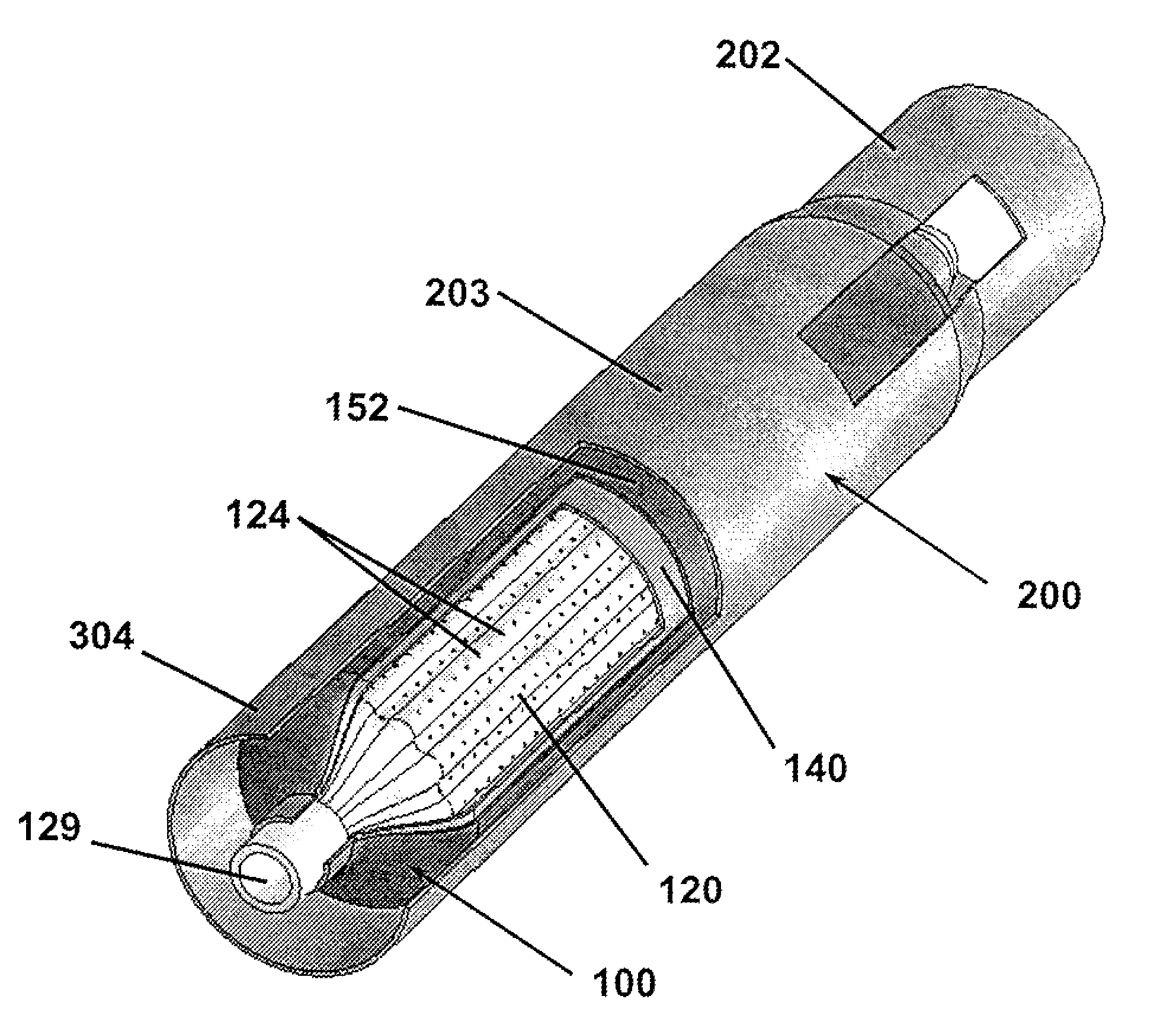
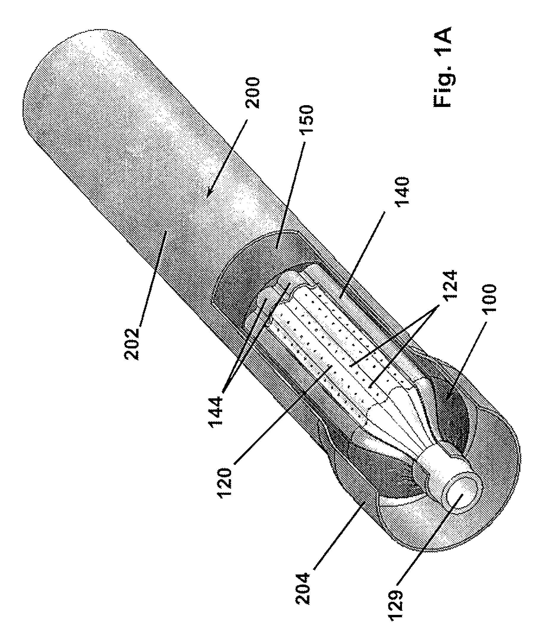
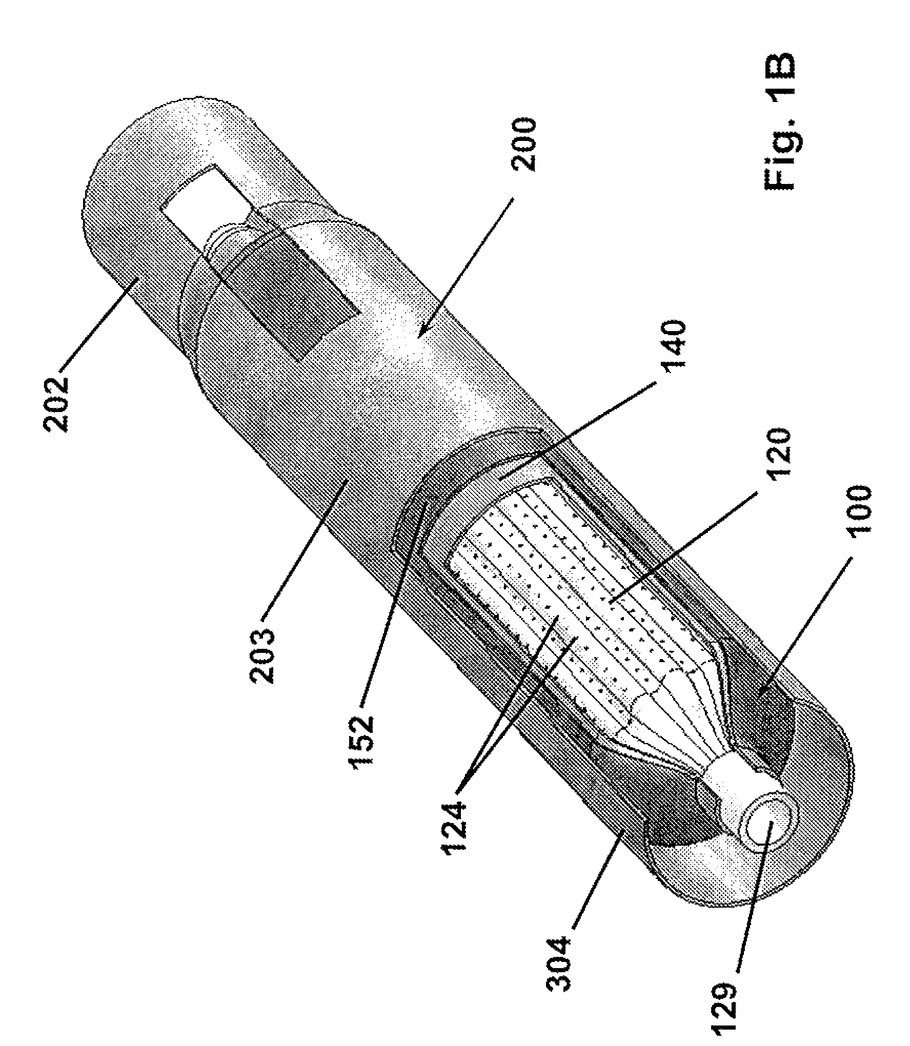
[0040]The present invention relates devices and methods for controlled expansion of tubular sections. An expandable bladder of this invention is formed about a structural element that maintains its shape in the linear direction and allows for the introduction of a pressurized fluid. In one preferred embodiment of the present invention, a novel bladder is formed over a removable shell which has been molded over a convoluted porous mandrel which in this embodiment forms the structural element. The bladder of this invention is formed incorporating reinforcing wound or woven fibers that are encapsulated in resilient fluid resistant bladder material. The bladder is capable of withstanding internal hydraulic pressures sufficient to controllably force expansion of a surrounding metallic tube without rupture and damage.

[0041]FIGS. 1A-B provide isometric views of the present invention according to one preferred embodiment. The apparatus 100 is shown in FIG. 1A in an unexpanded condition inse...


PUM

PropertyMeasurementUnit
angleaaaaaaaaaa
angleaaaaaaaaaa
angleaaaaaaaaaa

Abstract

The invention comprises a device for expanding tubular members to a controlled diameter and its method of fabrication. The device includes an expandable bladder held in a convoluted form. After the device is inserted into a cylindrical tube to be evenly expanded, the bladder is expanded by hydraulic pressure to a controlled maximum diameter. It is then deflated so the device can then be moved to another location and reused. The bladder is formed from a flexible impervious material having integral reinforcing fibers. It is initially formed in a fully expanded configuration over a convoluted mandrel and a removable cylindrical shell. When the shell is removed vacuum or external pressure draws the bladder against the mandrel. The bladder is overmolded with a resilient cover to hold it in reduced form until pressurized. The bladder cover prevents the bladder from kinking during the expansion.

Description

CROSS-REFERENCE TO RELATED APPLICATIONS[0001]This application claims the benefit of U.S. Provisional Application No. 60 / 874,378, filed Dec. 12, 2006 and entitled “Tubular Expansion Device and Method of Fabrication,” which is incorporated by reference herein.TECHNICAL FIELD[0002]The present invention relates to an improved tubular expansion apparatus for the controlled expansion of a tube segments and a method of fabrication thereof. The invention has application in a variety of disciplines such as the expansion of tubular casings (“tubulars”) in a well bore, the expansion of tubes in a heat exchanger, or the expansion of repair sleeves in either a heat exchanger or a pipeline, as well as other applications. Current methods of accomplishing these tasks are often ineffective in controlling the expansion of the tubular, risk collapsing the tubular due to axial loads applied to the tubular, or are significantly more expensive or time consuming.BACKGROUND[0003]The expansion of tube segme...

Claims


Application Information

Patent Timeline
Patent Type & Authority Patents(United States)
IPC IPC(8): F16L55/12
CPCE21B43/105F16L13/147F16L55/163F16L55/165F16L55/1653F16L55/1654F16L55/1657F28F9/16F28F11/00
Inventor FLY, CHARLES B.FLY, GERALD W.WALKER, KENNETH W.
Owner EXPANSION TECH
Why Eureka
Try Eureka