Multi-flute ball endmill for airfoil machining

a ball endmill and airfoil technology, applied in the direction of milling equipment, filing/raping tools, file, etc., can solve the problems of low productivity, difficult task of manufacturing ibr's, and cutters used for semi-finishing and finishing operations

Active Publication Date: 2011-01-04
PRATT & WHITNEY CANADA CORP
View PDF10 Cites 4 Cited by
  • Summary
  • Abstract
  • Description
  • Claims
  • Application Information

AI Technical Summary

Problems solved by technology

Manufacturing IBR's is a challenging task due to the complex geometry of airfoil surfaces.
However, such conventional milling cutters used for semi-finishing and finishing operations may suffer disadvantages of, for example, low productivity, poor airfoil surface finish, limited tool life, irrational us of expensive tool material, etc.

Method used


Image

  • Multi-flute ball endmill for airfoil machining
  • Multi-flute ball endmill for airfoil machining
  • Multi-flute ball endmill for airfoil machining

Examples


Embodiment Construction

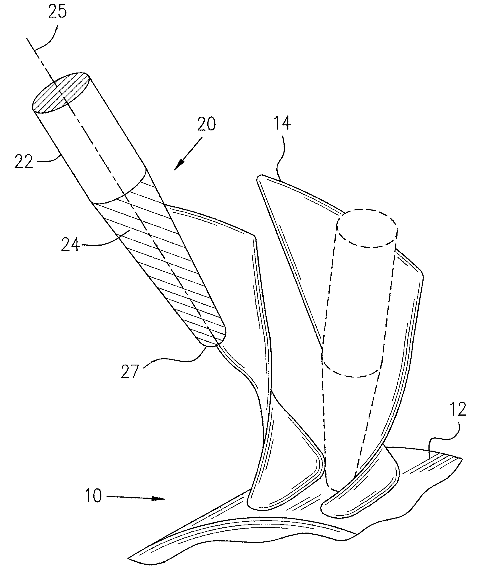
[0015]FIG. 1 schematically illustrates a milling cutter of the present invention generally indicated by numeral 20, used, for example, for machining an Integrally Bladed Rotor (IBR) generally indicated by numeral 10, of a gas turbine engine. IBR 10 comprises a hub 12 and a plurality of integral airfoils 14 projecting substantially radially outwardly therefrom. Manufacturing IBR's is a challenging task not only due to the complex geometry of airfoil surfaces, and to the material such as titanium or nickel alloys of which IBR's are usually made, but also due to the blade flexibility and tool low rigidity, which generate chatter vibrations during cutting process.

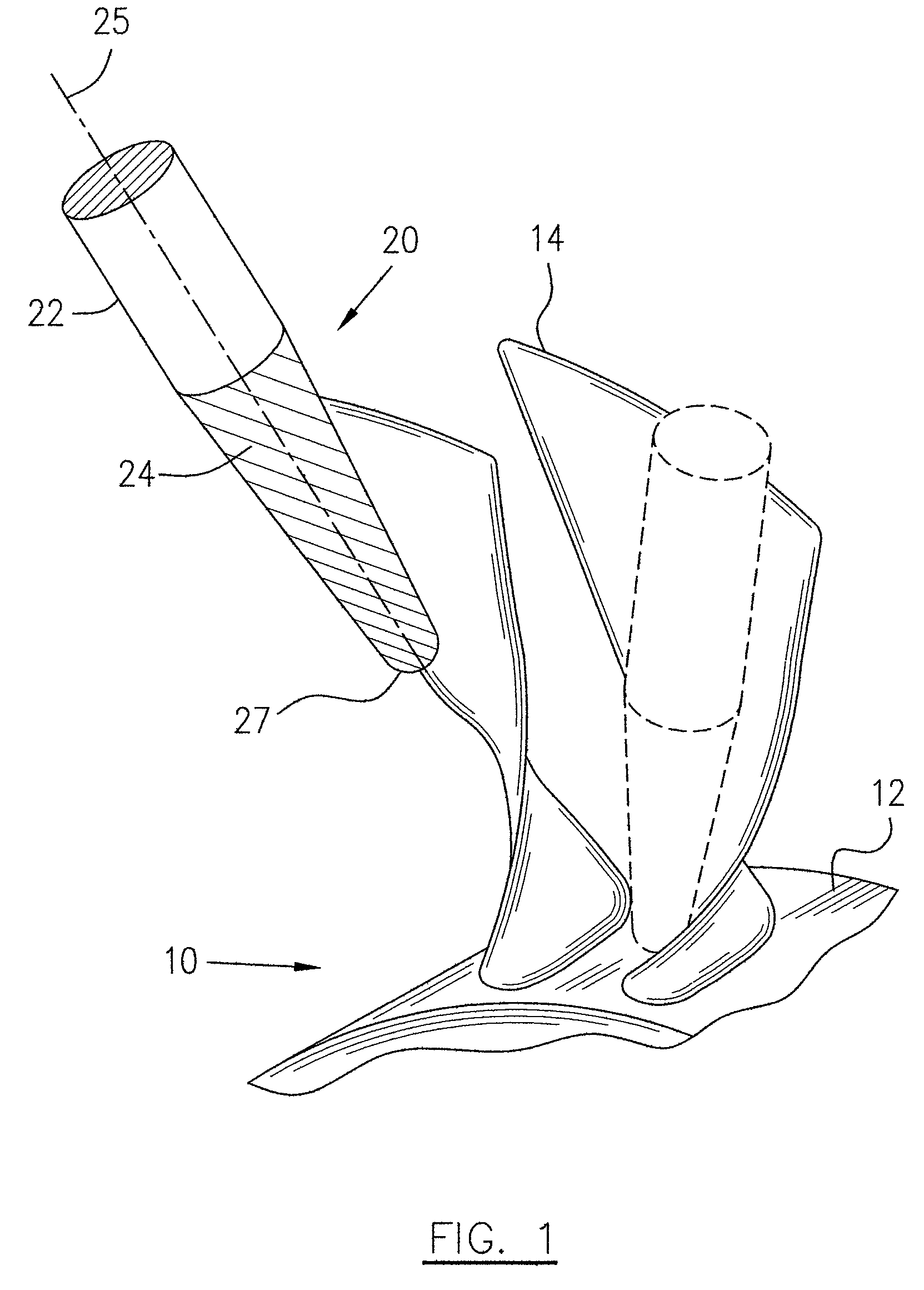
[0016]The milling cutter 20 according to one embodiment of the present invention generally includes a shank section 22 which is preferably substantially cylindrical, joined to a cutting section 24. The milling cutter 20 is adapted to be mounted to a spindle of a milling machine (not shown) to rotate about a longitudinal axis 25...


PUM


Abstract

A milling cutter comprises a shank section joined to a cutting section. The cutting section includes a plurality of peripheral teeth separated by a plurality of flutes to form cutting edges extending around the cutting section in a helix direction. The number of respective teeth and flutes is more than 12.

Description

TECHNICAL FIELD[0001]The invention relates generally to rotary milling cutters, and more particularly to improved milling cutters for machining an integral rotor blade disc of a gas turbine engine.BACKGROUND OF THE ART[0002]Integrally Bladed Rotors (IBR's), also commonly known as“bladed discs”are important parts of gas turbine engines. Manufacturing IBR's is a challenging task due to the complex geometry of airfoil surfaces. Existing methods of manufacturing IBR airfoils include flank milling, point milling, etc. In a flank milling process, the periphery of an end mill, typically a tapered ball end mill, generates the desired airfoil surface geometry through one or more passes of the cutter. The tool used in a point milling process is usually a tapered ball end style milling cutter. In both cases (flank and point milling) the tools are small enough such that the entire diameter of the tool can fit between the airfoils of the IBR. These milling cutters have cutting teeth and flutes w...

Claims


Application Information

Patent Timeline
Patent Type & Authority Patents(United States)
IPC IPC(8): B23B51/00B26D1/12
CPCB23C3/18B23C5/10B23C2210/086B23C2210/321Y10T407/1946B23C2210/486B23C2215/44Y10T407/1815Y10T407/1948B23C2210/326
Inventor SASU, IOANTURCOTTE, BERTRAND
Owner PRATT & WHITNEY CANADA CORP
Why Eureka
Try Eureka