Supercharge Your Innovation With Domain-Expert AI Agents!

Device for guiding a stream of air entering a combustion chamber of a turbomachine

a technology of turbomachines and airflow, which is applied in the direction of machines/engines, combustion air/fuel air treatment, liquid fuel engines, etc., can solve the problems of heavy and bulky fixing means, affecting the efficiency of combustion chambers, and reducing the flow of air through the device, so as to achieve simple, economical and effective

Active Publication Date: 2011-01-04
SN DETUDE & DE CONSTR DE MOTEURS DAVIATION S N E C M A
View PDF12 Cites 11 Cited by
  • Summary
  • Abstract
  • Description
  • Claims
  • Application Information

AI Technical Summary

Benefits of technology

[0007]According to the invention, just one of the shrouds of the flow straightener is formed as one with the diffuser, and the other shroud of the flow straightener is attached and fixed, for example welded, to the diffuser so that the device becomes a one-piece unit. The device according to the invention therefore does not require any special heavy and bulky fixing means, thus allowing the mass of the device to be reduced and making it possible not to restrict the aerodynamic function whereby the stream of air is guided by the device.
[0008]The invention is therefore a compromise between the manufacturing techniques hitherto used and allows the functions to be optimized while at the same time maintaining relative ease of manufacture. In particular, the shapes and sizes of the flow straightener can be optimized independently of those of the diffuser and are not restricted by the method used to produce the device, it being possible for the flow straightener to be complicated and to have a small radial dimension and a great many vanes. For example, when one of the shrouds of the flow straightener and the diffuser are formed as a single casting with the vanes of the flow straightener and the radial partitions of the diffuser, the casting cores are readily accessible for extraction because the other of the shrouds of the flow straightener is not present.
[0009]The invention makes it possible, in general, to save on the need to produce one of the shrouds of the flow straightener, because this shroud is cast with the diffuser. It also makes it possible to save on having to produce the flow straightener vanes, when these are cast with the diffuser.
[0010]In addition, it is simpler to manufacture and to install and allows a mass saving that is not insignificant over current techniques. It also reduces the risks of non-conformity, reduces manufacturing times and improves reliability because the flow straightener-diffuser assembly is ultimately a one-piece monobloc unit.
[0017]The inner shroud of the flow straightener advantageously comprises an annular axial rim collaborating with the inner wall of revolution of the diffuser to make it easier for the shroud to be positioned and fixed on the diffuser.

Problems solved by technology

However, the fixing means used are heavy and bulky and may create pressure drops in the flow of air through the device.
However, this technique is very restricted because it does not allow the functions to be optimized nor does it allow the production of complex flow straighteners, particularly flow straighteners comprising a great many vanes of small radial dimension (such as, for example, a flow straightener comprising over 100 vanes).
In particular, it is extremely complicated to cast a flow straightener and a diffuser as one because the casting cores that need to be inserted between the vanes of the flow straightener and the radial partitions of the diffuser are not very accessible and are therefore very difficult if not impossible to extract.

Method used


Image

  • Device for guiding a stream of air entering a combustion chamber of a turbomachine
  • Device for guiding a stream of air entering a combustion chamber of a turbomachine
  • Device for guiding a stream of air entering a combustion chamber of a turbomachine

Examples


Embodiment Construction

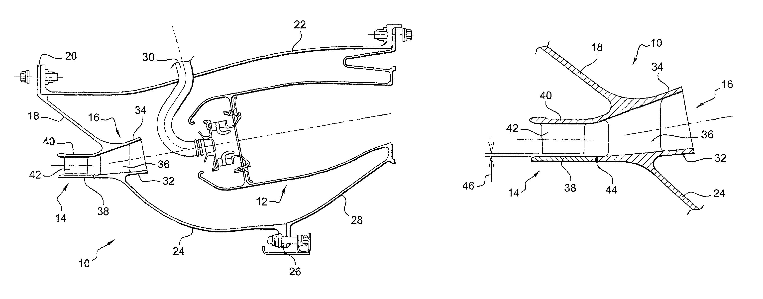
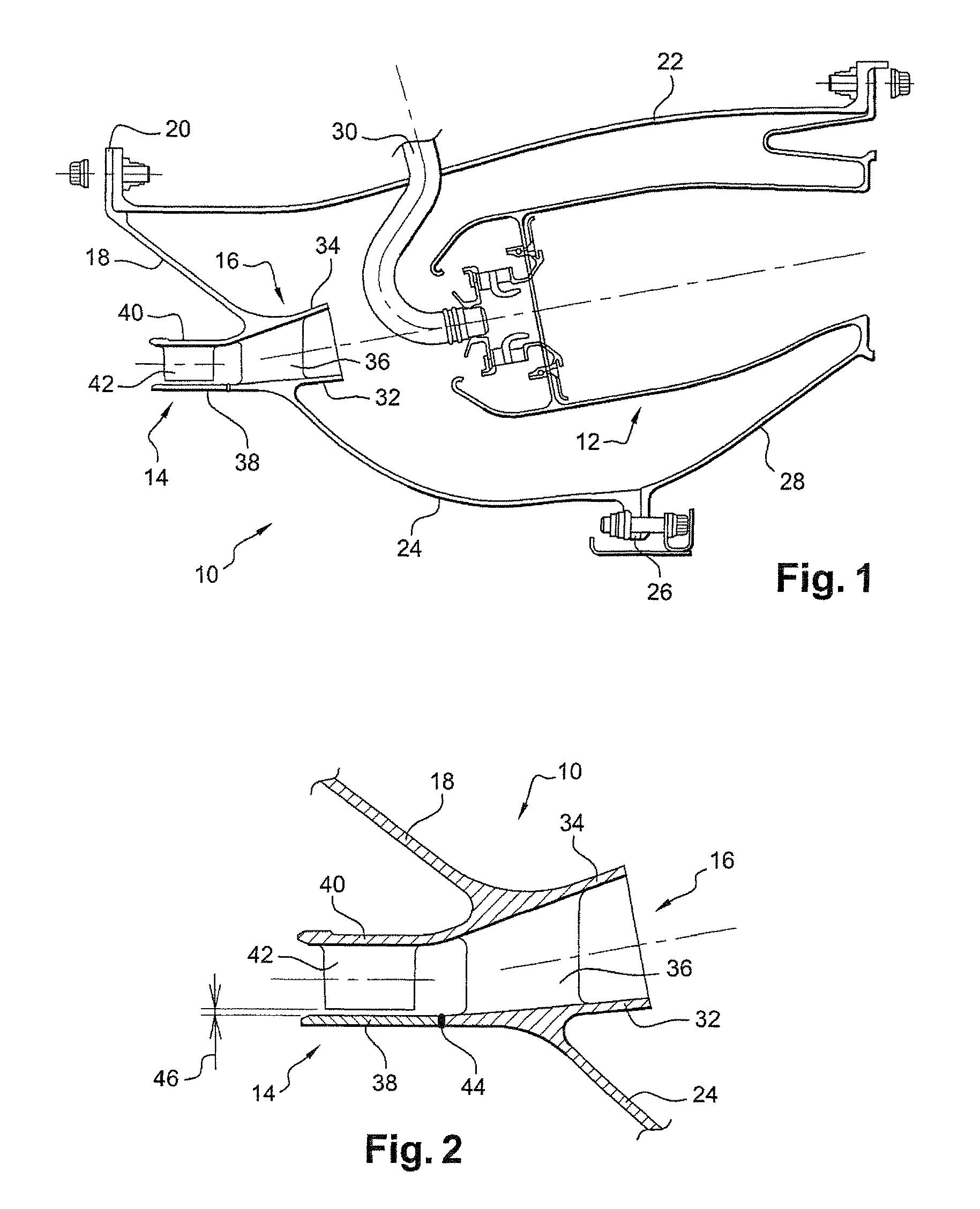
[0035]The device 10 according to the invention depicted in FIG. 1 is mounted axially between a compressor (not depicted) located upstream and a combustion chamber 12 of the turbomachine in order to straighten and guide the stream of air leaving the compressor and supplying air to the chamber 12 which itself feeds a turbine (not depicted) positioned downstream of the chamber.

[0036]This device 10 comprises, from the upstream direction downstream, a flow straightener 14 and a diffuser 16 which are joined together and supported by an outer frustoconical web 18 which diverges outward in the upstream direction and is fixed by an outer annular flange 20 to an outer casing 22 of the chamber and by an inner frustoconical web 24 which converges inward in the downstream direction and is fixed by an inner annular flange 26 to an inner casing 28 of the chamber 12.

[0037]The outer casing 22 of the chamber bears fuel injectors 30 uniformly distributed on a circumference about the longitudinal axis ...


PUM


Abstract

A device for guiding a stream of air entering a combustion chamber of a turbomachine is disclosed. The device includes a flow straightener followed by a diffuser. One of the flow straightener shrouds is formed as one with one wall of revolution of the diffuser. The other flow straightener shroud is added and attached to the other wall of revolution of the diffuser. The vanes of the flow straightener are secured by one end to one shroud of the flow straightener and separated by a small clearance from the other shroud at their other end.

Description

BACKGROUND OF THE INVENTION[0001]The present invention relates to a device for guiding a stream of air entering a combustion chamber of a turbomachine, such as an aircraft turbojet or turboprop engine.[0002]A device of this type is positioned at the outlet of a compressor and comprises a flow straightener followed by a diffuser, the diffuser comprising two coaxial walls of revolution joined together by radial partitions and the flow straightener comprising two coaxial shrouds axially aligned with the two walls of revolution of the diffuser respectively, and between which substantially radial vanes extend.DESCRIPTION OF THE PRIOR ART[0003]In the state of the art, it is known practice to form the flow straightener and the diffuser independently of one another in order to optimize their shape, their size and their function, and then for the downstream end of the flow straightener to be fixed by appropriate means to the upstream end of the diffuser. However, the fixing means used are he...

Claims


Application Information

Patent Timeline
Patent Type & Authority Patents(United States)
IPC IPC(8): F01D9/04
CPCF01D9/041F01D9/044F02C7/04F05D2230/232Y02T50/673F05D2230/21F05D2240/12Y02T50/671F04D29/542Y02T50/60
Inventor DAGUENET, LUC HENRI CLAUDE
Owner SN DETUDE & DE CONSTR DE MOTEURS DAVIATION S N E C M A
Features
  • R&D
  • Intellectual Property
  • Life Sciences
  • Materials
  • Tech Scout
  • Unparalleled Data Quality
  • Higher Quality Content
  • 60% Fewer Hallucinations
Learn More