Fluid circulation system
a circulation system and fluid technology, applied in the field of fluid mechanics, can solve problems such as significant energy expenditur
- Summary
- Abstract
- Description
- Claims
- Application Information
AI Technical Summary
Benefits of technology
Problems solved by technology
Method used
Image

Examples
first embodiment
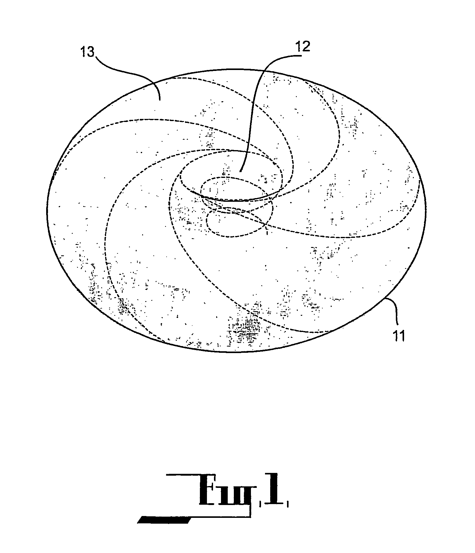
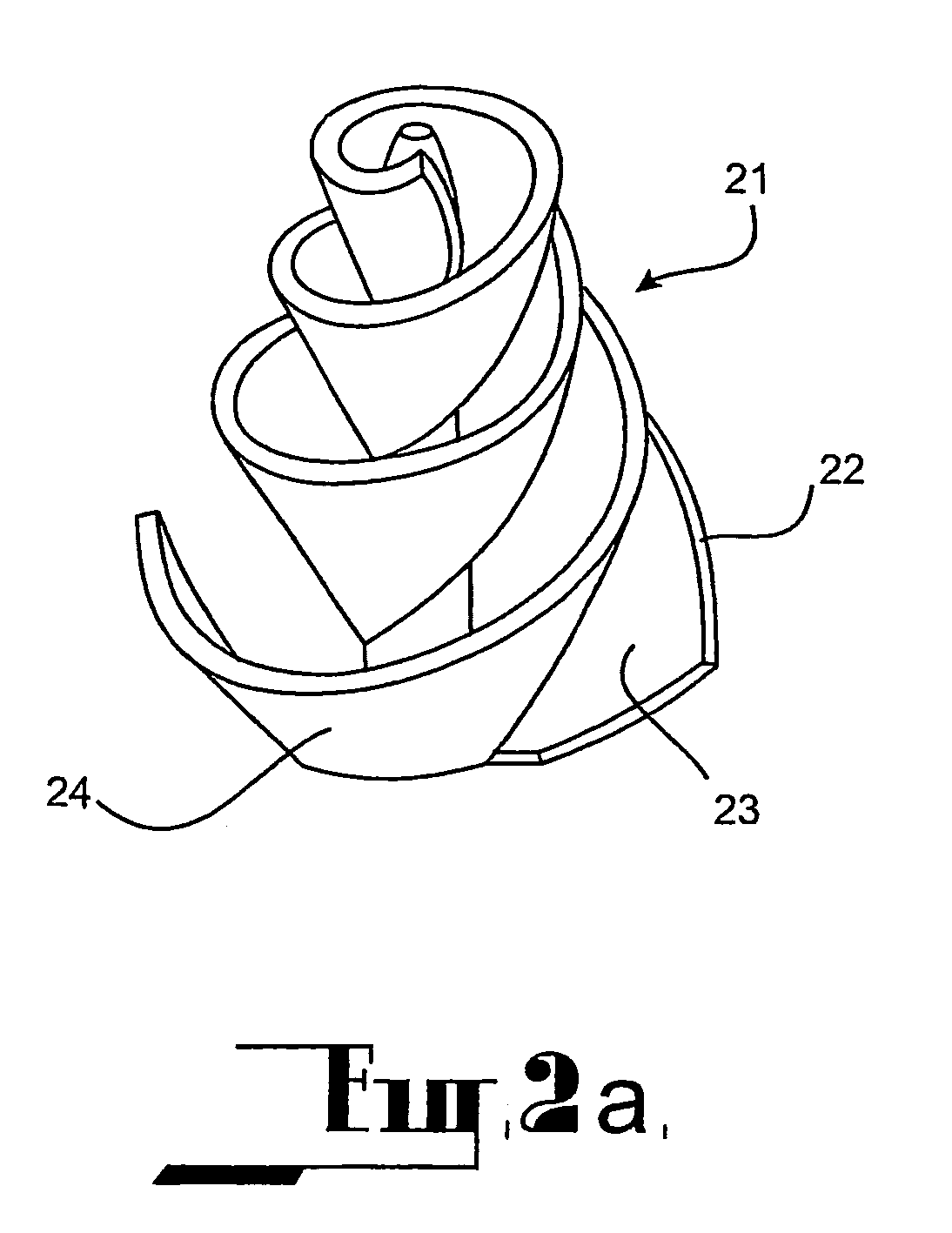
[0044]In the present invention as diagrammatically represented in FIG. 4 there is depicted a body of liquid 31 held in a cylindrical tank 32, the tank 32 being oriented with its central axis vertical. Within the tank 32, there is mounted a submersible motor 33 having an impeller 34, the axle of the motor and impeller being substantially co-axially aligned with the central axis of the tank 32. The motor 33 may be conveniently mounted to the base of the tank 35. As mentioned above, the impeller 34 is designed so that its active surfaces conform to the Golden Section as shown in FIG. 2a or FIG. 2b. Operation of the impeller 34 causes the fluid to circulate as a ring vortex and indicated by the flow lines 36, as discussed above. If the liquid 31 is a mixture which must be mixed homogeneously, such mixing is achieved efficiently.
[0045]The advantages of the present system will be better appreciated by a comparison with a conventional mixing system of similar arrangement. Such a system aga...
second embodiment
[0051]In a second embodiment as shown in FIG. 5, there is provided a water remediaton system for a water tower of the type used in water reticulation systems for municipal supplies. Water towers are widely used by water authorities as a means to provide an adequate supply of water at the desired pressure during periods of peak demand. During non-peak periods, water is pumped by a pumping station, with a portion of the water meeting the demand and a portion being pumped into an elevated water tower. During peak periods when the demand exceeds the capacity of the pumping system, additional supply is obtained from the water tower. It is normal design with such towers for water to be input and withdrawn through the same pipe which is connected at or near the floor of the water storage. However, this leads to a problem. Through much of the year, the volume of water added to the tank and withdrawn from the tank is only a small proportion of the total capacity. At least in the warmer month...
third embodiment
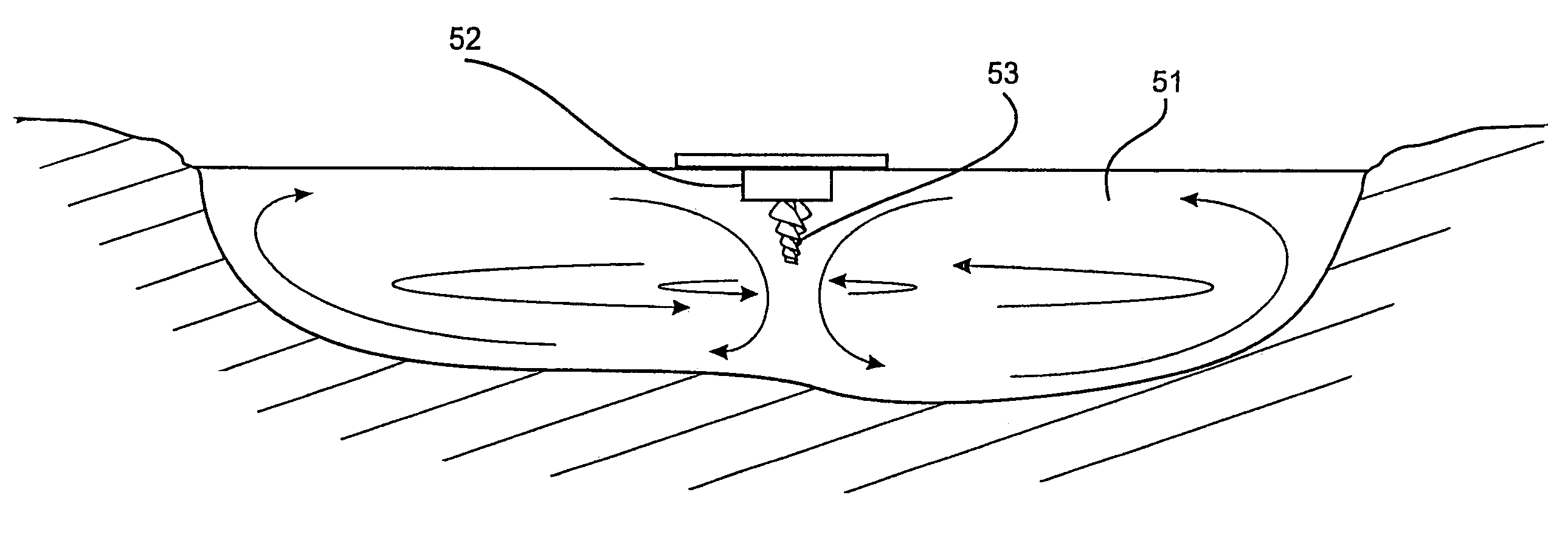
[0053]In a third embodiment as shown in FIG. 6, there is provided a water remediation and / or maintenance system for a pond, such as may be found in municipal parks. It is well known that such ponds suffer fouling due to lack of aeration which results in the death of fish and aerobic plants and the build up of unpleasant mould, fungi, botulism, and mosquito breeding. With a still pond, water stratifies with the cold water remaining at the bottom and the warmer water at the top which accentuates the problems. Attempts to reduce the fouling by aeration or other means have been only partially effective because they do not fully circulate the water but rather rely on diffusion of compressed air into the stagnant lower layers. Because of the stratification, this diffusion is not very successful.
[0054]In the third embodiment, a pond 51 is provided with a small motor 52 driving an impeller 53 of the type described for the first embodiment. The motor 52 is located approximately in the centre...
PUM
| Property | Measurement | Unit |
|---|---|---|
| power | aaaaa | aaaaa |
| surface area | aaaaa | aaaaa |
| radius | aaaaa | aaaaa |
Abstract
Description
Claims
Application Information
 - R&D
- Intellectual Property
- Life Sciences
- Materials
- Tech Scout
- Unparalleled Data Quality
- Higher Quality Content
- 60% Fewer Hallucinations
Browse by: Latest US Patents, China's latest patents, Technical Efficacy Thesaurus, Application Domain, Technology Topic, Popular Technical Reports.
© 2025 PatSnap. All rights reserved.Legal|Privacy policy|Modern Slavery Act Transparency Statement|Sitemap|About US| Contact US: help@patsnap.com