DC/DC converter control circuit, and power supply apparatus, light emitting apparatus and electronic device using the same

a technology of dc/dc converter and control circuit, which is applied in the direction of electric variable regulation, process and machine control, instruments, etc., can solve the problems of overcurrent flow and delay in overcurrent protection respons

Inactive Publication Date: 2011-01-04
ROHM CO LTD
View PDF13 Cites 11 Cited by
  • Summary
  • Abstract
  • Description
  • Claims
  • Application Information

AI Technical Summary

Benefits of technology

[0013]After detecting the short-circuit state and halting the switching operation of the switching transistor for a predetermined halt time, the switching controller may begin the start-up of the separately excited DC / DC converter once again. At a time of a short-circuit of the load, in cases in which a long-term short-circuit of the load is maintained, by halting the switching transistor for the predetermined halt time, since there is intermittent operation in which current flows during the start-up time and is shut off during the halt time, it is possible to prevent a large current flowing continuously in the switching transistor or transformer.
[0019]The switching controller may include a pulse width modulator which generates a pulse signal, a driver circuit which drives the switching transistor based on a pulse signal, and a hysteresis comparator which compares the output voltage and a threshold voltage set in a vicinity of a target value of the output voltage. The pulse width modulator may gradually change a duty ratio of the pulse signal in the start-up mode, and, in the normal mode and the halt mode, may fix the duty ratio of the pulse signal at a predetermined value; and the driver circuit may drive the switching transistor based on the pulse signal in the start-up mode and the normal mode, and may halt driving of the switching transistor in the halt mode.
[0020]In such cases, it is possible to execute a soft start in the start-up mode. In addition, in the normal mode, since the switching transistor is driven at the fixed duty ratio, irrespective of the output voltage, the output voltage gradually increases. After that, when the output voltage reaches a first threshold voltage of the hysteresis comparator, the switching transistor is halted, and the output voltage gradually decreases. When the output voltage decreases to a second threshold voltage of the hysteresis comparator, driving of the switching transistor is restarted. As a result, in the normal mode, the output voltage is stabilized between the first threshold voltage and the second threshold voltage. Furthermore, by putting the machine into a halt mode when there is a short-circuit, a step-up operation can be halted and the circuit protected.
[0025]According to this embodiment, it is possible to preferably protect the switching transistor and the transformer of the separately excited DC / DC converter from overcurrent.
[0027]According to this embodiment, when the light-emitting element, which is a load, is driven normally without a short-circuit or the like occurring, it is possible to stably emit light from the light-emitting element, and in cases of a short-circuit, it is possible to protect the circuit from overcurrent.
[0029]According to this embodiment, in cases in which the light-emitting element, which is connected to the power supply apparatus as a load, short-circuits, it is possible to prevent a large current from flowing out continuously for a long time from the battery, and it is possible to curtail heat generation in the electronic device.

Problems solved by technology

However, in the technology described in the abovementioned document, in which the current on the primary side of the transformer is monitored, when a load suddenly short-circuits, there have been cases in which current flowing on the primary side of the transformer suddenly rises at a speed exceeding response speed of a voltage comparator, so that overcurrent protection response is delayed, and the overcurrent flows in the switching transistor.

Method used


Image

  • DC/DC converter control circuit, and power supply apparatus, light emitting apparatus and electronic device using the same
  • DC/DC converter control circuit, and power supply apparatus, light emitting apparatus and electronic device using the same
  • DC/DC converter control circuit, and power supply apparatus, light emitting apparatus and electronic device using the same

Examples


Embodiment Construction

[0037]The invention will now be described based on preferred embodiments which do not intend to limit the scope of the present invention but exemplify the invention. All of the features and the combinations thereof described in the embodiment are not necessarily essential to the invention.

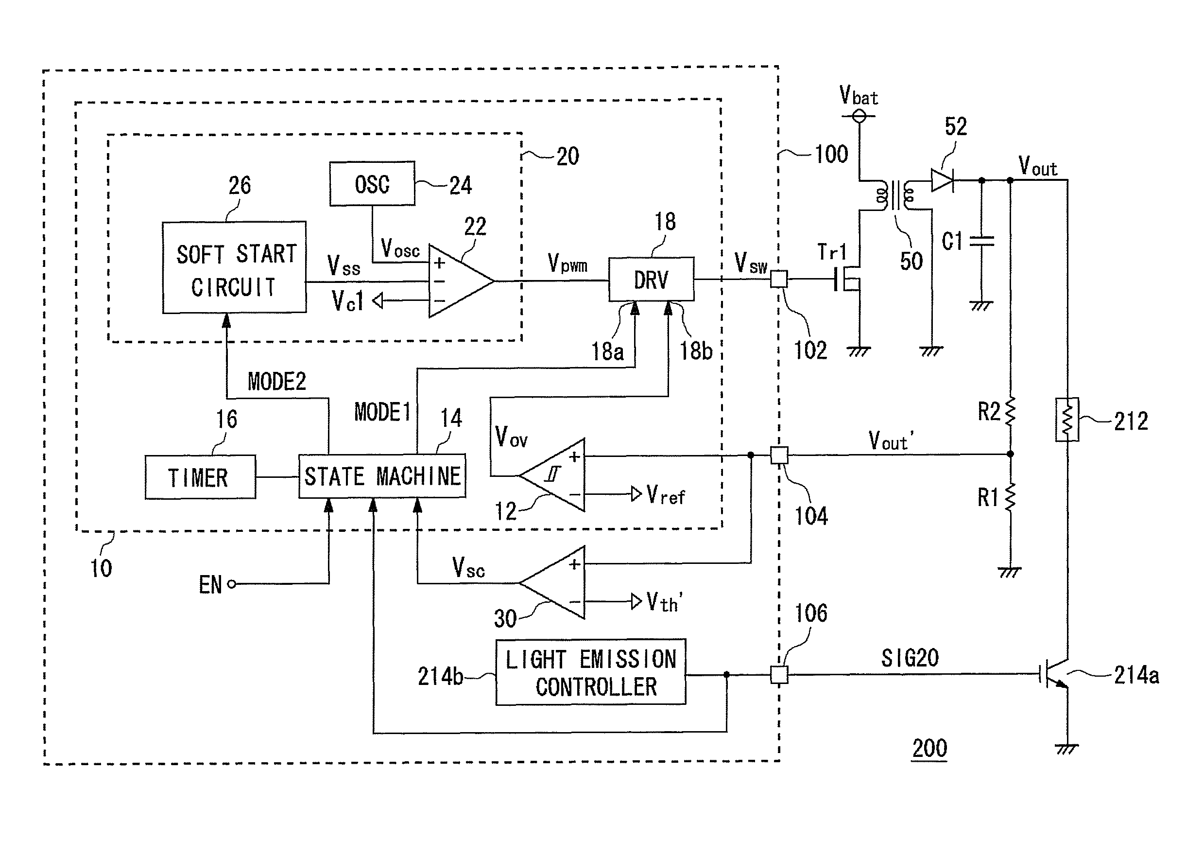
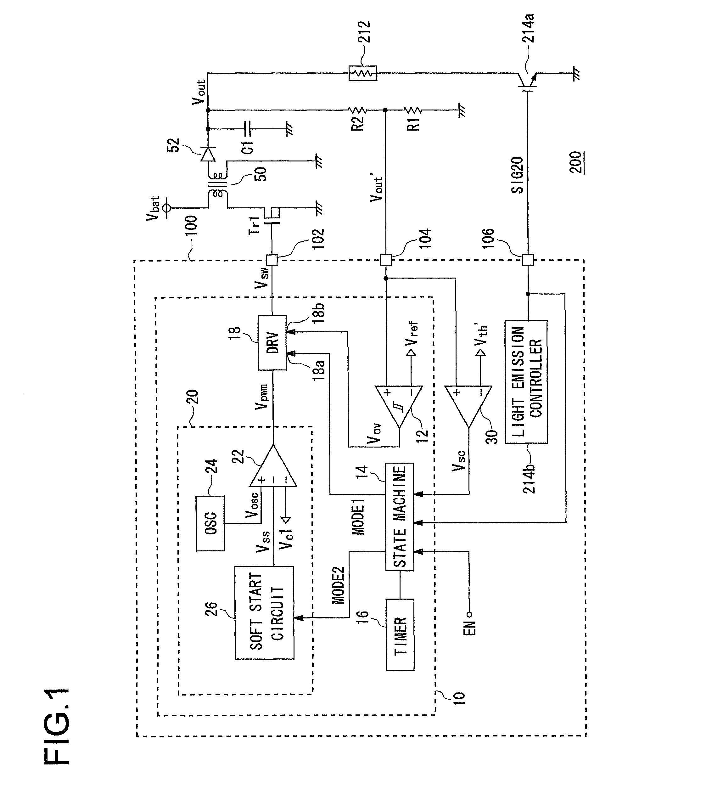
[0038]FIG. 1 is a circuit diagram showing a configuration of a light-emitting device 200 according to the embodiment. This light-emitting device 200 is installed in an electronic device provided with a camera, and when an image is taken by the camera, functions as a light source used as a flash.

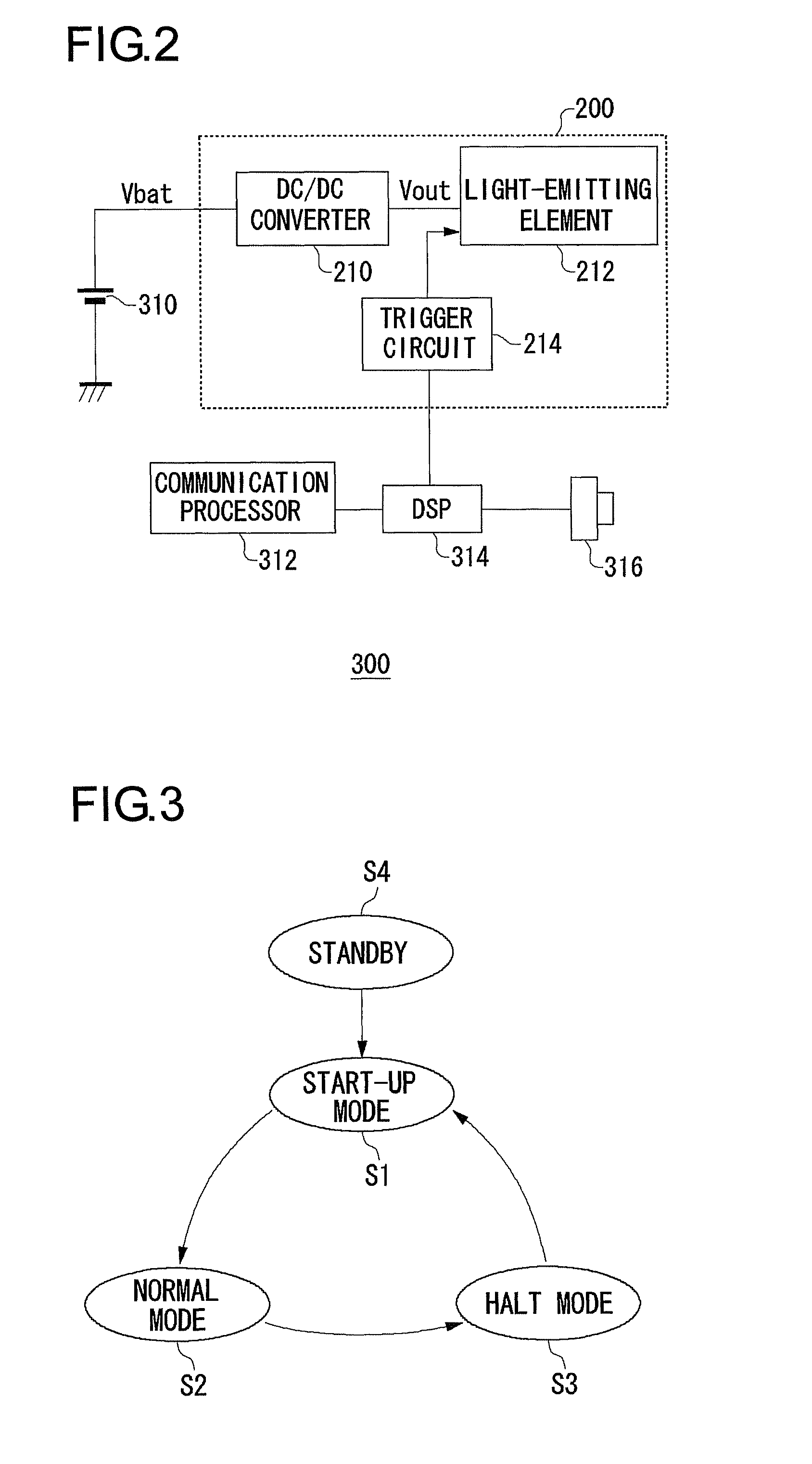
[0039]FIG. 2 is a block diagram showing a configuration of the electronic device 300 in which the light-emitting device of FIG. 1 is installed. In the present embodiment, the electronic device 300 is a mobile telephone in which a camera is installed, and is provided with a battery 310, a communication processor 312, a DSP (Digital Signal Processor) 314, an imaging unit 316, and the light-emitting device 200....


PUM


Abstract

A control circuit is provided for a separately excited DC / DC converter which directly monitors output voltage to detect a short-circuit state, and performs overcurrent protection. A switching controller of the control circuit controls a switching operation of a switching transistor of the separately excited DC / DC converter. A voltage comparator compares the output voltage and a threshold voltage, to detect the short-circuit state. After a predetermined start-up time has elapsed after beginning start-up of the separately excited DC / DC converter, when the voltage comparator detects the short-circuit state, the switching controller halts the switching operation of the switching transistor, and makes detection of the short-circuit state by the voltage comparator non-operative before elapse of the start-up time. After detecting the short-circuit state and halting the switching operation of the switching transistor for a predetermined halt time, the switching controller begins start-up of the separately excited DC / DC converter once again.

Description

CROSS REFERENCE TO RELATED APPLICATIONS[0001]This is a Continuation of International Application No. PCT / JP2006 / 311065, filed on 2 Jun. 2006. Priority under 35 U.S.C. §119(a) and 35 U.S.C. §365(b) is claimed from Japanese Application No. 2005-166046, filed 6 Jun. 2005, the disclosure of which is also incorporated herein by reference.BACKGROUND OF THE INVENTION[0002]1. Field of the Invention[0003]The present invention relates to a switching power supply, and a drive system for a DC / DC Converter.[0004]2. Description of the Related Art[0005]A step-up type of switching power supply for generating voltage higher than an input voltage is widely used in various electronic devices. This step-up type of switching power supply is provided with a switching element, and an inductor or a transformer, and by putting the switching element ON or OFF in a time-division way, a back electromotive force is generated in the inductor or the transformer, and input voltage is stepped up and outputted.[0006...

Claims


Application Information

Patent Timeline
Patent Type & Authority Patents(United States)
IPC IPC(8): G05F1/00
CPCH02M1/32H02M3/33507H02H7/12
Inventor TAMEGAI, YOICHIYAMAMOTO, ISAOARAKI, KYOICHIRO
Owner ROHM CO LTD
Why Eureka
Try Eureka