Internal combustion engine for a vehicle comprising at least one compressor cylinder at least one compressor cylinder connected to a compressed-air tank

a technology of internal combustion engine and compressor cylinder, which is applied in the direction of machines/engines, non-mechanical valves, transportation and packaging, etc., can solve the problems of increasing fuel price and vibration in the vehicle, and achieve the effect of convenient manufacturing

Inactive Publication Date: 2013-04-25
FREEVALVE
View PDF1 Cites 16 Cited by
  • Summary
  • Abstract
  • Description
  • Claims
  • Application Information

AI Technical Summary

Benefits of technology

[0008]It is another object of the present invention to provide an internal combustion engine, that admit use of a super charger optimized for large exhaust gas flows without the arise of turbo lag / delay.
[0009]It is another object of the present invention to provide an internal combustion engine, that readily can be manufactured by converting an existing internal combustion engine.SUMMARY OF THE INVENTION
[0014]Preferable the first compressed-air conduit comprises regenerator that is located between the outlet valve of the compressor cylinder and the compressed-air tank. The advantage of using a regenerator is that the warm compressed-air from the compressor cylinder heats the regenerator at the same time as the compressed-air is cooled down which entail that more compressed-air can be stored in a compressed-air tank of given size. According to another preferred embodiment the second compressed-air conduit is connected to the first compressed-air conduit between the regenerator and the outlet valve of the compressor cylinder, which entail that the compressed-air that is lead to the inlet valve actuators and the outlet valve actuators is first lead through the regenerator in order to heated once again. The advantage of leading warm compressed-air to the inlet valve actuators and the outlet valve actuators is that the compressed-air when heated expands and thus lasts to more activations of the inlet valve actuators and outlet valve actuators.
[0016]In a preferred embodiment the first inlet opening of the working cylinder is connected to a first inlet manifold, in which an ejector nozzle mouths, a third compressed-air conduit extends from the compressed-air tank to said ejector nozzle, said third compressed-air conduit comprising a maneuverable flow valve that is arranged to open and close fluid communication from the compressed-air tank to the ejector nozzle. This result in that compressed-air by choice can be supplied to the inlet valves which gives a higher fill ratio in the working cylinders.

Problems solved by technology

However, during the last decades the public have put forward great demands upon faster development of more environment friendly and fuel efficient internal combustion engines concurrently with the increase in the fuel price.
Moreover, it can be a problem of internal combustion engines that vibrations arises in the vehicle as well as in the power train of the vehicle due to the fact that the combustion pulse moment arising in the cylinders of the internal combustion engine upon combustion therein is not in balance due to the fact that the symmetry of the combustion pulse pattern of the internal combustion engine cannot be achieved for one reason or another.

Method used


Image

  • Internal combustion engine for a vehicle comprising at least one compressor cylinder at least one compressor cylinder connected to a compressed-air tank
  • Internal combustion engine for a vehicle comprising at least one compressor cylinder at least one compressor cylinder connected to a compressed-air tank
  • Internal combustion engine for a vehicle comprising at least one compressor cylinder at least one compressor cylinder connected to a compressed-air tank

Examples


first embodiment

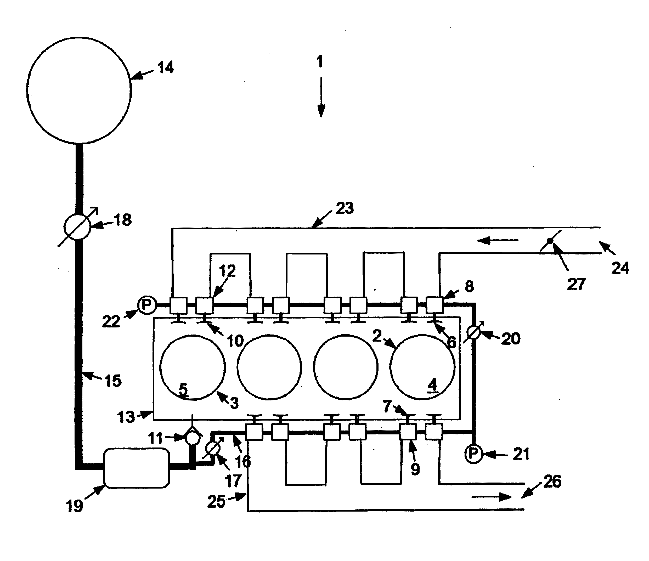
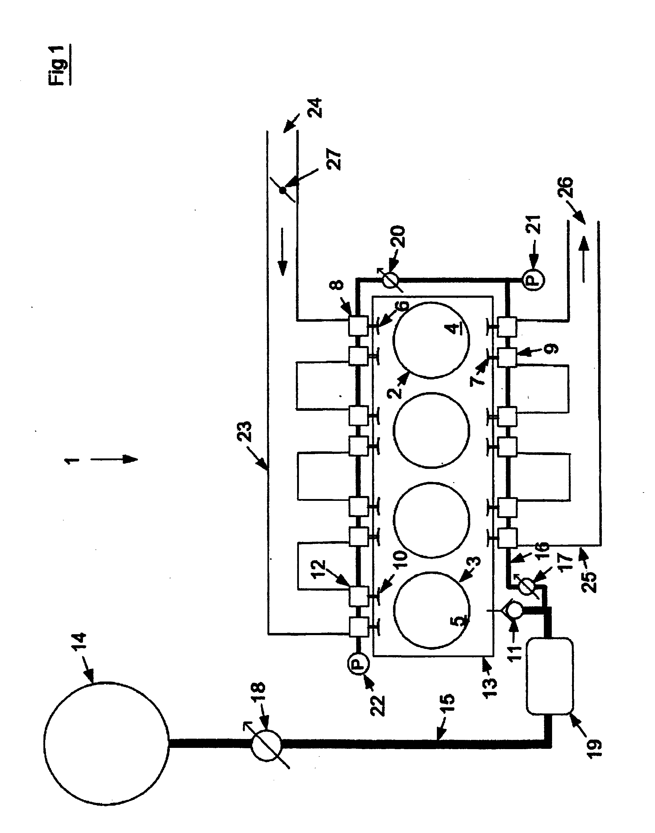
[0030]Reference at first hand is made to FIG. 1, in which is shown an inventive internal combustion engine, generally designated 1, according to a The internal combustion engine 1 comprises at least one working cylinder 2 and at least one compressor cylinder 3. In the shown embodiment the internal combustion engine 1 comprises three working cylinders and one compressor cylinder, however, this ratio may be any other if the specific application so admit or demands. The working cylinder 2 comprises a working piston 4 movably arranged in the working cylinder 2, which working piston 4 is arranged to increase and decrease, respectively, a volume defined jointly by the working cylinder 2 and the working piston 4. Correspondingly the compressor cylinder 3 comprises a working piston 5 movably arranged in the compressor cylinder 3.

[0031]Furthermore, the working cylinder 2 comprises a first inlet opening and a first inlet valve 6 arranged to open and close said first inlet opening, an outlet ...

third embodiment

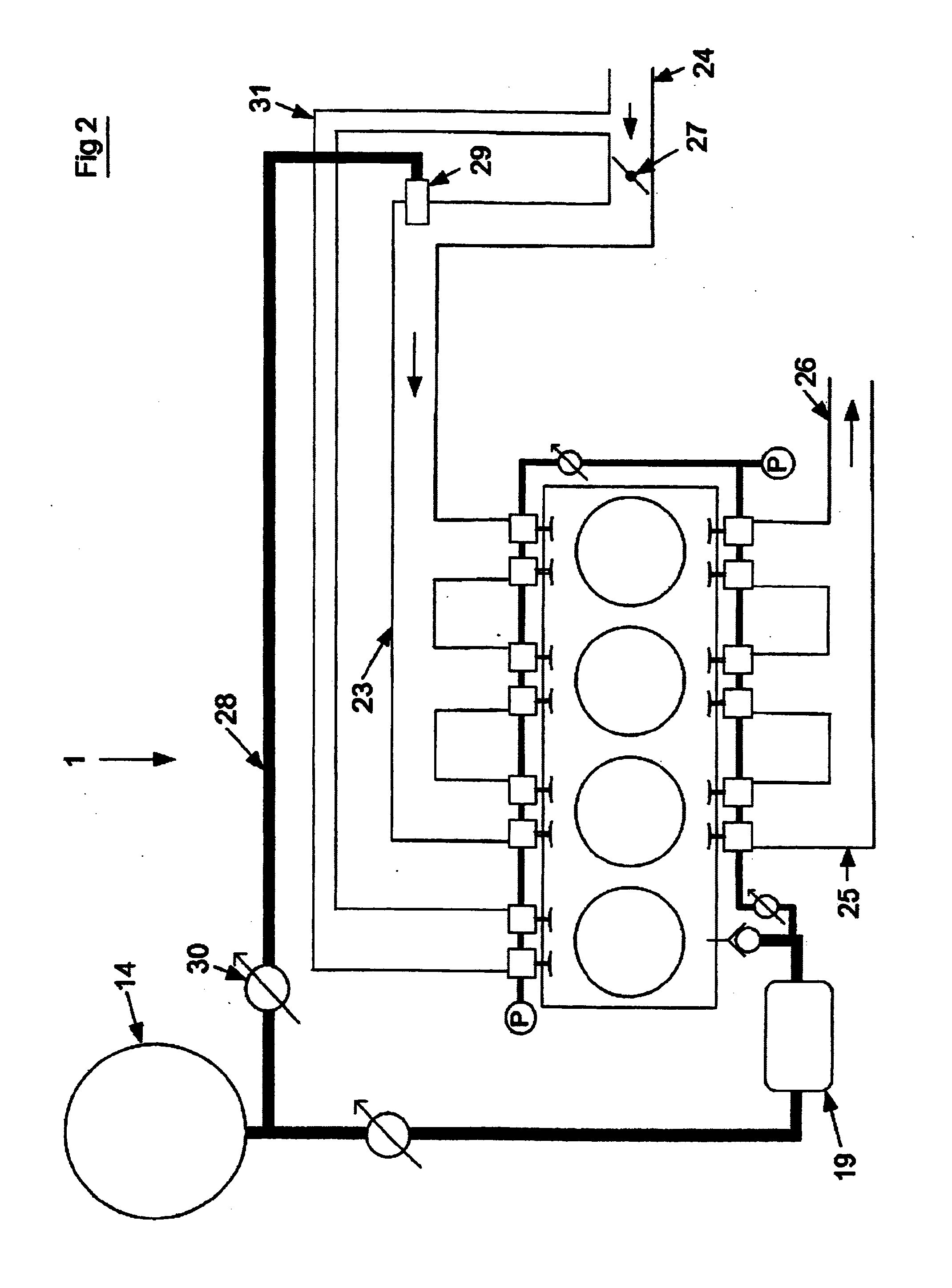
[0041]Reference is now also made to FIGS. 2 and 3, in which a second and a third embodiment, respectively, of the inventive internal combustion engine 1 are shown.

[0042]The shown embodiments comprises a third compressed-air conduit 28 that extends from the compressed-air tank 14 to an ejector nozzle, or compressed-air nozzle, 29, and that comprises a maneuverable flow valve 30 arranged to open and close fluid communication from the compressed-air tank 14 to the ejector nozzle 29. The ejector nozzle 29 mouth in the first inlet manifold 23 and is directed in the flow direction of the inlet air. The compressed-air led via the third compressed-air conduit 28 from the compressed-air tank 14 is in the preferred embodiment cool down, such as described above in connection with FIG. 1 and the regenerator 19. Compressed-air is led into the first inlet manifold 23 via the ejector nozzle 29 in order to increase the fill rate of the working cylinder (see FIG. 2), alternatively in the working cyl...

fifth embodiment

[0046]Reference is now also made to FIG. 5, in which is shown a fifth embodiment, which is a combination of the internal combustion engines according to FIG. 3 and FIG. 4. In addition to what have been described in connection with FIGS. 2-4, the first air supply conduit 31 comprises a maneuverable flow distribution valve 38 that is connected to the second air supply conduit 37 and that is arranged to alternating admit flow communication between the first inlet opening of the compressor cylinder 3 and the air inlet 24, and the first inlet opening of the compressor cylinder 3 and the air supply conduit 37, respectively. This entail that the compressor cylinder 3 can be fed with the air source, air inlet 24 or the super charger 32, having the highest or the most suitable pressure at the moment. Thereto, it is preferred that when the flow distribution valve 38 admits fluid communication between the first inlet opening of the compressor cylinder 3 and the air inlet 24 fluid communication...


PUM


Abstract

An internal combustion engine includes a working cylinder (2) including an inlet valve (6) and an adherent pneumatic inlet valve actuator (8), an outlet valve (7) and an adherent pneumatic outlet valve actuator (9), and a working piston (4), a compressor cylinder (3) including an inlet valve (10), an outlet valve (11), and a compressor piston (5) operated by the working piston (4), a compressed-air tank (14) connected to the compressor cylinder (3) via a first compressed-air conduit (15), and a second compressed-air conduit (16) that extends from the first compressed-air conduit (15), the first inlet valve actuator (8) and the outlet valve actuator (9) of the working cylinder (2) being connected to the second compressed-air conduit (16).

Description

TECHNICAL FIELD OF THE INVENTION[0001]The present invention relates in general to an internal combustion engine for a vehicle. In specific the present invention relates to a internal combustion engine for a vehicle, comprising at least two cylinders, a moveably arranged piston being arranged in each cylinder in order to increase and decrease, respectively, a volume defined jointly by the cylinder and the piston, and a compressed-air tank connected to at least one of said at least two cylinders.BACKGROUND OF THE INVENTION AND PRIOR ART[0002]Internal combustion engines for vehicles have been available since the middle of the 1800-century and have all the time been the object of development driven forward concurrently with the development of the manufacturing industries. However, during the last decades the public have put forward great demands upon faster development of more environment friendly and fuel efficient internal combustion engines concurrently with the increase in the fuel ...

Claims


Application Information

Patent Timeline
Patent Type & Authority Applications(United States)
IPC IPC(8): F02B75/04F01L9/10F01L9/16
CPCF02B33/22F02B75/04F02B37/00F02B33/44F01L9/16F01L9/10B60K6/12B60W30/18127F02B33/06
Inventor CARLSON, URBANHOGLUND, ANDERSVON KOENIGSEGG, CHRISTIAN
Owner FREEVALVE
Why Eureka
Try Eureka