Machine control system and method

a technology of machine control and control system, applied in the direction of machine control, process control, navigation instruments, etc., can solve the problems of inability to see parts of the job site behind, to the side of, or far away from the machine, and the physical limitations of the machine operator

Active Publication Date: 2011-01-04
CATERPILLAR INC
View PDF86 Cites 44 Cited by
  • Summary
  • Abstract
  • Description
  • Claims
  • Application Information

AI Technical Summary

Problems solved by technology

However, the machine operator may have physical limitations.
For example, the machine operator may have a limited field of vision, and may be incapable of seeing portions of the job site behind, to the side of, or far away from the machine.
Further, the machine operator's view may be obstructed by obstacles at the job site, or even components of the machine itself.
However, use of the sensors may not solve other issues, such as machine operator fatigue.
Thus, the visual sensor is not designed to recognize terrain features, such as piles, trenches, and the like, that may be located throughout a job site.
Furthermore, the visual sensor does not provide an overall 3-D terrain map of the job site areas outside of the area defined by the two beacons.

Method used


Image

  • Machine control system and method
  • Machine control system and method
  • Machine control system and method

Examples


Embodiment Construction

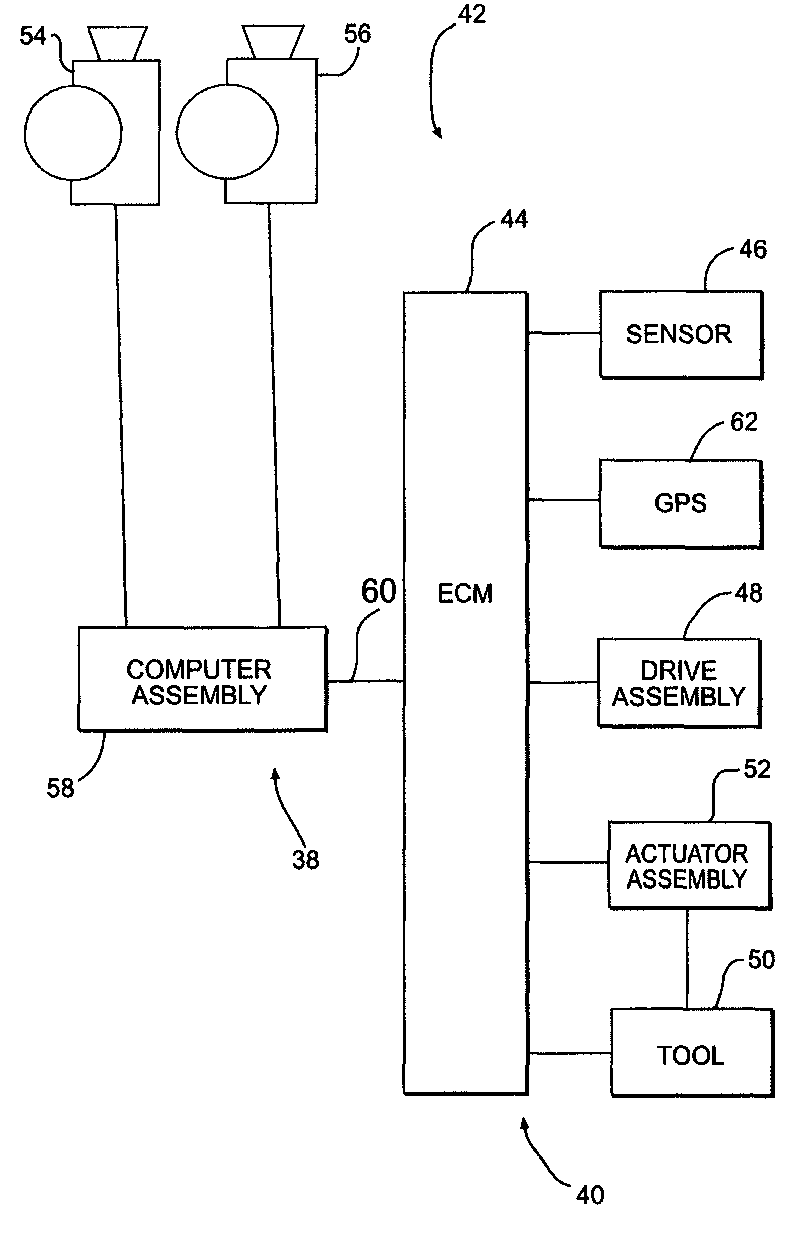
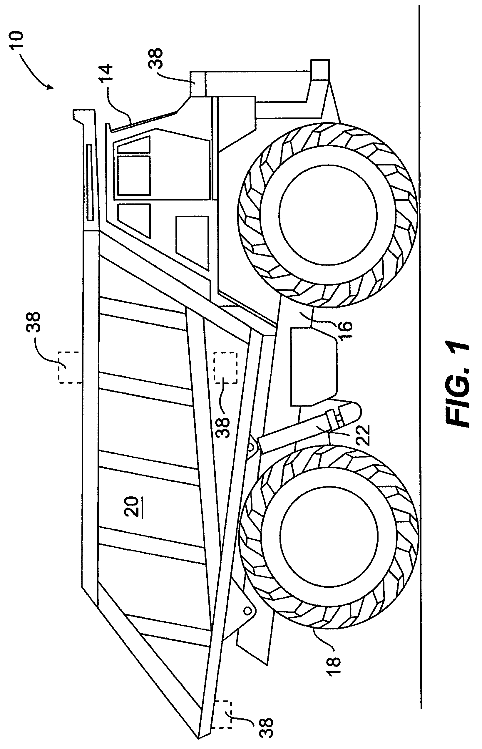
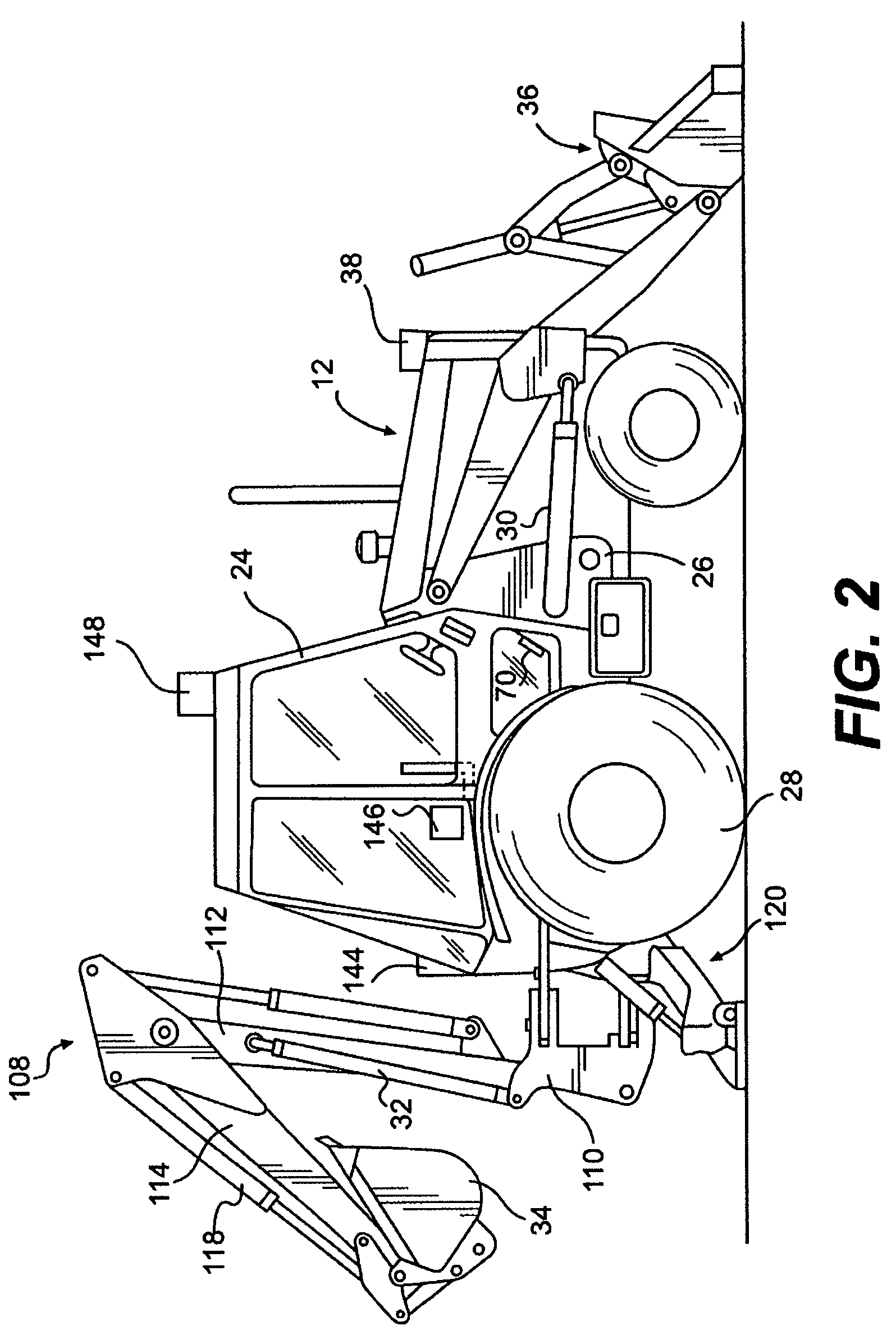
[0020]FIGS. 1 and 2 illustrate exemplary machines 10 and 12. Machine 10 of FIG. 1 may include a truck. Machine 10 may include, for example, a cab 14 for a machine operator, a frame or body 16, a drive assembly 18, a container 20 for storing material, and an actuator assembly 22 for actuating container 20. Machine 12 of FIG. 2 may include a backhoe loader. Machine may include a cab 24 for a machine operator, a frame or body 26, a drive assembly 28, work implements or tools 34 and 36, and actuator assemblies 30 and 32 for lifting, lowering, or otherwise actuating tools 34 and 36. Machines 10 and 12 may be used at job sites to perform various operations including, for example, transporting material, lifting, lowering, digging, filling, and other operations that would be apparent to one skilled in the art. It should be understood that machines 10 and 12 are exemplary only, and that aspects of this disclosure may be employed on excavators, on-highway vehicles, dozers, and / or any other su...


PUM


Abstract

A machine control system may include a machine mounted stereo imaging apparatus configured to provide a 3-D model indicative of a terrain feature. The machine control system may also include a control module configured to process the 3-D model, and automatically perform an operation with a work tool based on the characteristics of the 3-D model.

Description

TECHNICAL FIELD[0001]The present disclosure relates generally to a control system and method, and relates more particularly to a machine control system and method involving the use of a stereo camera system.BACKGROUND[0002]Machines may be employed at a job site to perform a variety of operations. Those operations may include, for example, carrying loads, moving earth, digging, and dumping. The machines used may include, for example, trucks, backhoes, excavators, dozers, and loaders. These machines may include implements or tools configured to assist with performing the aforementioned operations. The machines and their associated tools may be operated and controlled by machine operators.[0003]A machine operator may sit in a cab containing machine controls, such as a steering wheel, joystick, and / or any other control device suitable for operating the machine. Additionally or alternatively, the machine operator may be located off-site, and may operate the machine with a remote control ...

Claims


Application Information

Patent Timeline
Patent Type & Authority Patents(United States)
IPC IPC(8): G06F19/00
CPCE02F3/434E02F3/437E02F3/842E02F9/205G05D1/0251G05D1/0274G05D1/0278G05D2201/0202
Inventor PRICE, ROBERT J.BRANDT, EVERETT G.
Owner CATERPILLAR INC
Why Eureka
Try Eureka