Remote chassis monitoring system

a chassis monitoring and remote monitoring technology, applied in error detection/correction, instruments, digital computers, etc., can solve the problems of indirect inspection, inconvenient maintenance, high cost and inefficiency, and increase the cost of maintaining a telephone connection

Inactive Publication Date: 2011-01-04
RACKMASTER SYST
View PDF12 Cites 13 Cited by
  • Summary
  • Abstract
  • Description
  • Claims
  • Application Information

AI Technical Summary

Benefits of technology

[0011]This system facilitates a rapid and repeated monitoring of remote computing stations in real time. The system is functional, even when one of the monitored computing stations is down. The system can be independent of the configurations of particular monitored computing stations. Finally, the system can be implemented at relatively low cost, by using the internet or other shared or mutual communications linkage.
[0030]The monitoring system uses an existing TCP / IP network connection to provide a convenient and inexpensive communication link, regardless of whether the connection is over a local area network, over a wide area network, or over the Internet. Although generally less preferred, the system can employ a direct connection among network computers as well. Status information with respect to each chassis is maintained by a monitoring system governed by a microcontroller independently of the principal computing function at the chassis. As an option, the system can incorporate out-of-band monitoring in which the queries from the monitoring station and the web pages from the monitored stations are transmitted over an interconnection separate from the network interconnection used for primary data and program transmissions. This enables the monitoring system to function even if the primary communication channels are down.
[0032]With respect to the entire network, configuring the monitoring program to generate independent threads individually and uniquely associated with the monitored stations, prevents a failure to connect with a particular chassis from delaying or otherwise undesirably affecting the monitoring process with respect to the other chassis in the network.

Problems solved by technology

However, in the case of wide area networks (WAN) or networks of computers linked via the Internet, the computing stations of the network typically are separated from one another by distances that render direct inspection costly and inefficient.
However, this involves an added expense of maintaining a telephone connection dedicated to the remote, monitored location, and functions well only when the computer platform being monitored is operative.
A fault detected in the managed computer results in a message sent to the managing computer and a resulting display at the managing computer.

Method used


Image

  • Remote chassis monitoring system
  • Remote chassis monitoring system
  • Remote chassis monitoring system

Examples


Embodiment Construction

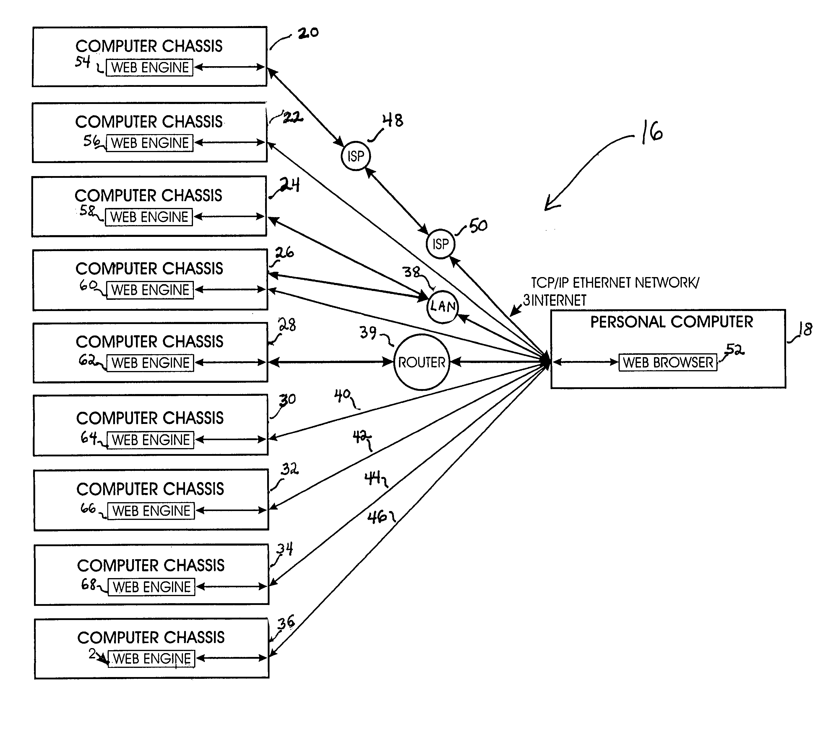
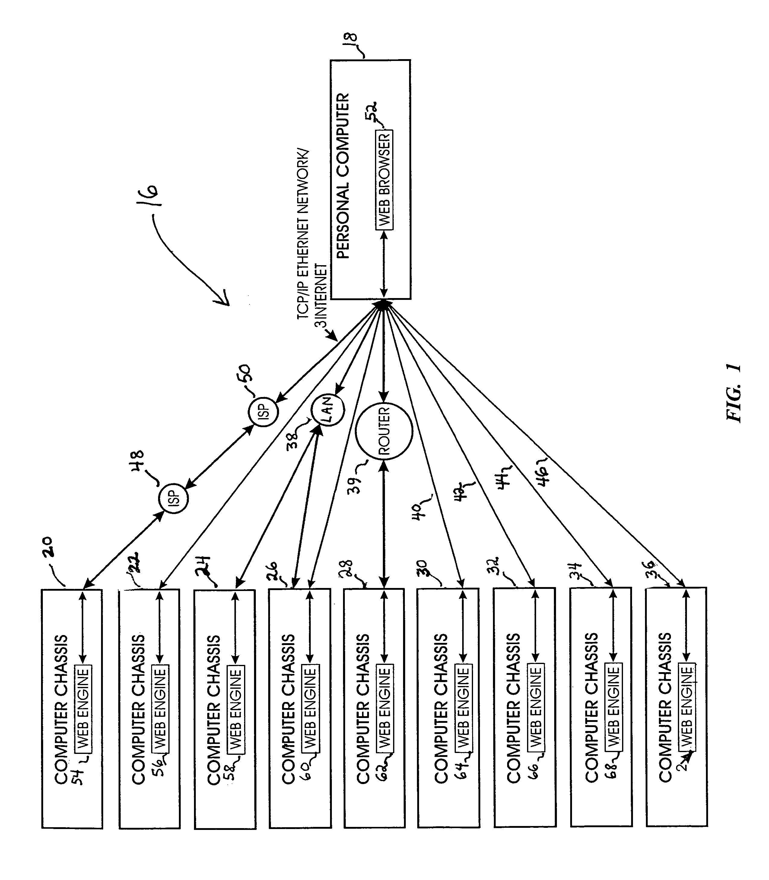
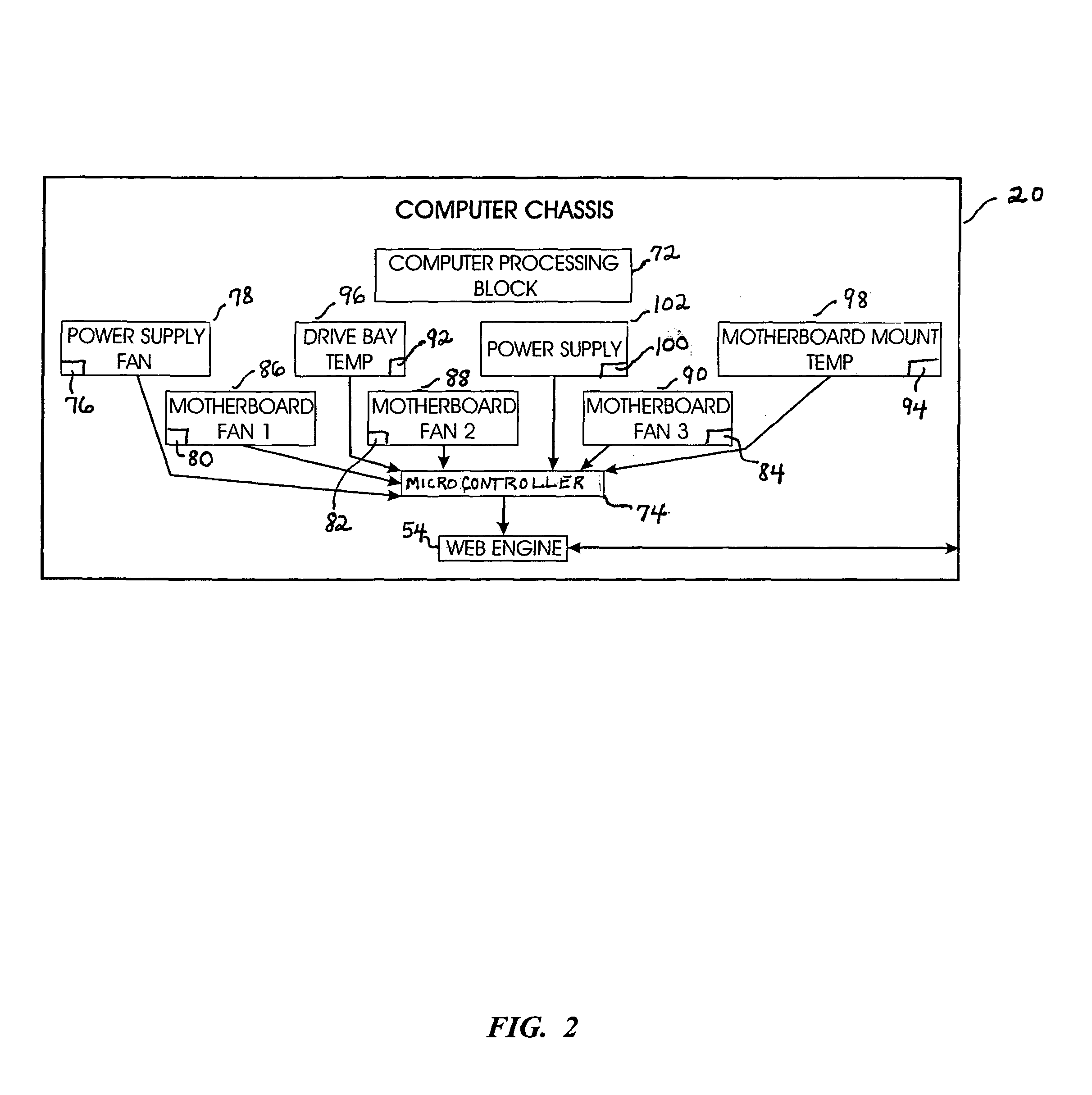
[0043]Turning now to the drawings, there is shown in FIG. 1 an information processing network 16 including multiple computers or computing stations, one of which is a monitoring station 18. The remaining computing stations, shown as computer chassis 20-36, are monitored by station 18. The monitoring station can be a personal computer. Chassis or stations 18 and 20-36 are interconnected over a TCP / IP (transmission control protocol / internet protocol) network connection. Several interconnection modes are illustrated: a local area network (LAN) in which computer 18 and computing stations 24 and 26 are coupled to a hub 38; a wide area network (WAN) in which chassis 28 and computer 18 are coupled to a router indicated at 39; direct links 40-46 between computer 18 and chasses 30-36; and an Internet connection involving two Internet service providers (ISPs) 48 and 50 as intermediaries between computing station 20 and computer 18.

[0044]It is to be appreciated that these alternatives are show...


PUM


Abstract

In a system for monitoring remote computing stations, each remote station includes an array of detectors and a controller configured to receive the detector signals. The controller causes a condition information generator to generate condition records including multiple condition information entries, each entry corresponding to one of the detector outputs. A monitoring station is adapted to send cues to the remote stations, and each station responds to a cue by presenting its condition record as a web page for retrieval by the monitoring station. The monitoring station sends the cues to stations in a sequence controlled by a user of the monitoring station, or alternatively, in a rapid and repeated sequence according to a station selection program written in Java or another universal language. The program generates interlocked instruction sets designed to recognize, as an error, a failure to connect with a remote station. The system incorporates a comparator function for matching each condition information entry with an acceptance standard, and generating a fault indication if the entry fails to satisfy the standard.

Description

[0001]This application claims the benefit of priority based on Provisional Application No. 60 / 415,180 entitled “Remote Chassis Monitoring System,” filed Oct. 1, 2002.BACKGROUND OF THE INVENTION[0002]The present invention is concerned with monitoring conditions at remote chassis or computing stations, and more particularly with systems designed for individual, approximately real-time monitoring of multiple computing stations in an information processing network.[0003]In organizations that depend on the efficient processing and transfer of information, the networking of multiple computers is a common practice. Networking considerably enhances the capacity of each computer on the system, by enabling a rapid transfer of information among the system computers, and by enabling the system computers to share operating programs and other tools used to process system information. As computer networks become increasingly sophisticated and complex, the interdependence among the network computer...

Claims


Application Information

Patent Timeline
Patent Type & Authority Patents(United States)
IPC IPC(8): G06F11/00
CPCG06F11/2294H04L43/0817
Inventor JESTER, SCOTT A.
Owner RACKMASTER SYST
Why Eureka
Try Eureka