Method of manufacturing an ink-jet recording head
a technology of inkjet recording head and manufacturing method, which is applied in the direction of recording equipment, recording information storage, instruments, etc., can solve the problems of inability to achieve accurate control limit the improvement of the inability to accurately control the depth of the ink inlet passage, etc., to achieve the effect of high accuracy, low cost and low production cos
- Summary
- Abstract
- Description
- Claims
- Application Information
AI Technical Summary
Benefits of technology
Problems solved by technology
Method used
Image
Examples
first embodiment
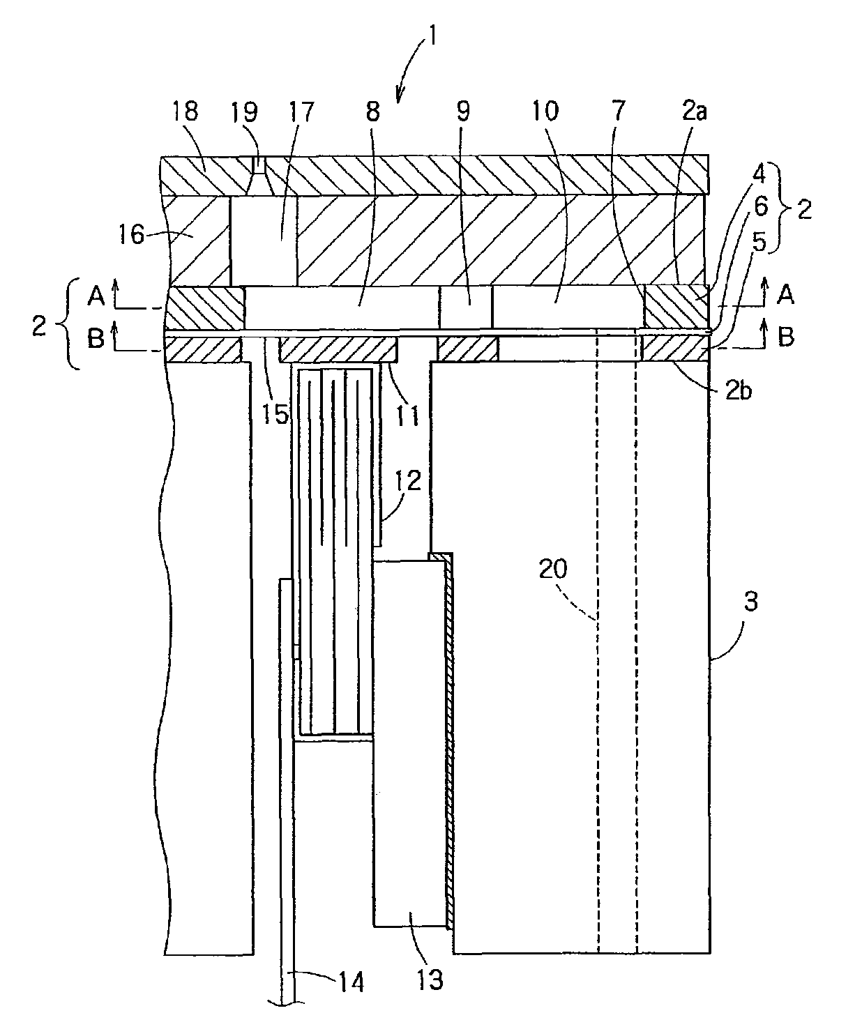
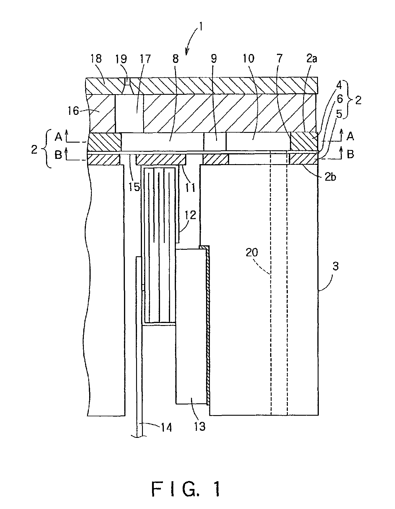
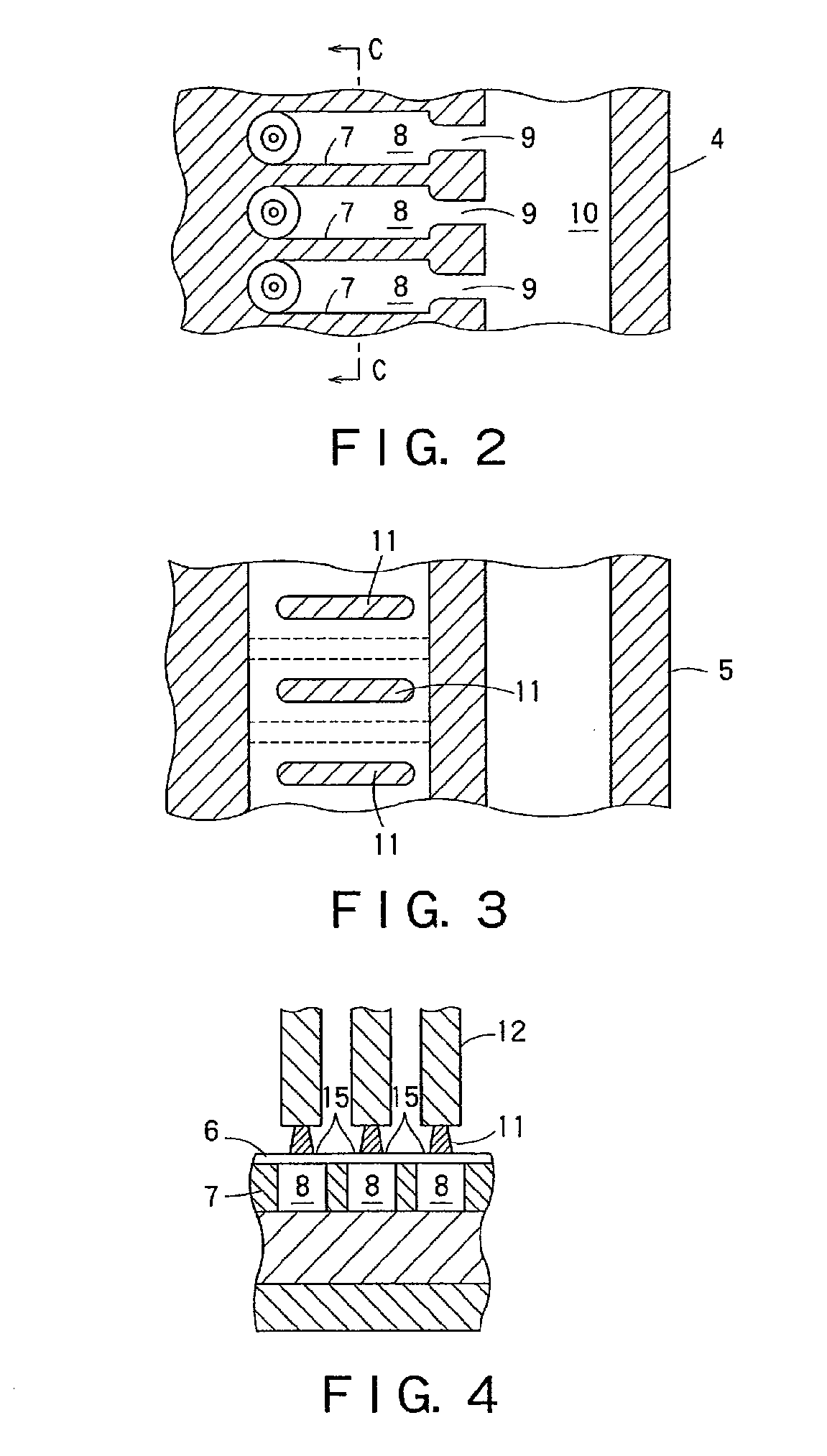
[0141]A method of manufacturing the ink-jet recording head in the first embodiment will be described hereinafter. The plate-shaped member 2 is formed by sandwiching the intermediate layer 6 between the first layer 4 and the second layer 5. The plate-shaped member 2 may be any one of those shown in FIGS. 5A, 5B and 5C. The plate-shaped member 2 shown in FIG. 5A has an intermediate layer 6 formed of a polyimide resin (PI), and a first layer 4 and a second layer 5 formed of a stainless steel. The intermediate layer 6 may be formed of titanium. Various materials may be used in proper combinations for forming the first layer 4, the second layer and the intermediate layer 6. Essentially, a combination of materials is determined selectively so that the first layer 4 and the second layer 5 can be etched selectively over the intermediate layer 6.
[0142]The plate-shaped member 2 shown in FIG. 5B has an intermediate layer 6 formed of a polymeric material, such as PPS, and a first layer 4 and a ...
sixth embodiment
[0175]A passage unit included in an ink-jet recording head in a sixth embodiment according to the present invention will be described with reference to FIGS. 12A and 12B, in which parts like or corresponding to those of the ink-jet recording head shown in FIGS. 11A, 11B and 11C are denoted by the same reference characters and the description thereof will be omitted. This ink-jet recording head employs piezoelectric vibrators 106A of a flexural vibration mode. A vibrating unit formed by sandwiching the piezoelectric vibrator 106A between an upper electrode 116 and a lower electrode 117 is attached to the vibrating plate 105 included in the passage unit 101.
[0176]The piezoelectric vibrators 106A are driven for flexural vibrations by driving signals to change the pressure in the pressure chambers 107 to jet ink particles through the nozzle holes 108. The ink-jet recording head in the sixth embodiment is the same in operation and effect as that in the fifth embodiment shown in FIGS. 11A...
seventh embodiment
[0183]FIG. 14 shows an ink-jet recording head in a seventh embodiment according to the present invention, which is similar to the ink-jet recording head shown in FIGS. 11A, 11B and 11C and hence parts like or corresponding to those of the ink-jet recording head shown in FIGS. 11A, 11B and 11C are denoted by the same reference characters and the description thereof will be omitted.
[0184]As shown in FIG. 14, the first base plate 120 is provided with the connecting holes 121 and auxiliary ink storage chambers 109A formed by etching. The auxiliary ink storage chambers 109A are additional ink storage chambers aligned with the ink storage chambers 109 formed in the second base plate 122.
[0185]Thus, the ink-jet recording head in the seventh embodiment is provided additionally with the auxiliary ink storage chambers 109A for the effective use of space. The ink storage chambers 109 and the auxiliary ink storage chambers 109A provide a sufficiently large ink storage volume, reduce passage res...
PUM
 Abstract
Description
Claims
Application Information
 - R&D
- Intellectual Property
- Life Sciences
- Materials
- Tech Scout
- Unparalleled Data Quality
- Higher Quality Content
- 60% Fewer Hallucinations
Browse by: Latest US Patents, China's latest patents, Technical Efficacy Thesaurus, Application Domain, Technology Topic, Popular Technical Reports.
© 2025 PatSnap. All rights reserved.Legal|Privacy policy|Modern Slavery Act Transparency Statement|Sitemap|About US| Contact US: help@patsnap.com


