Compact power semiconductor package and method with stacked inductor and integrated circuit die
a technology of integrated circuit dies and semiconductors, applied in the field of electrical system packaging, can solve the problems of compact integration of power inductor and power controller ic dies
- Summary
- Abstract
- Description
- Claims
- Application Information
AI Technical Summary
Benefits of technology
Problems solved by technology
Method used
Image
Examples
first embodiment
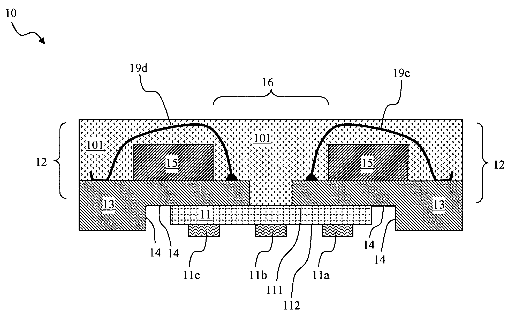
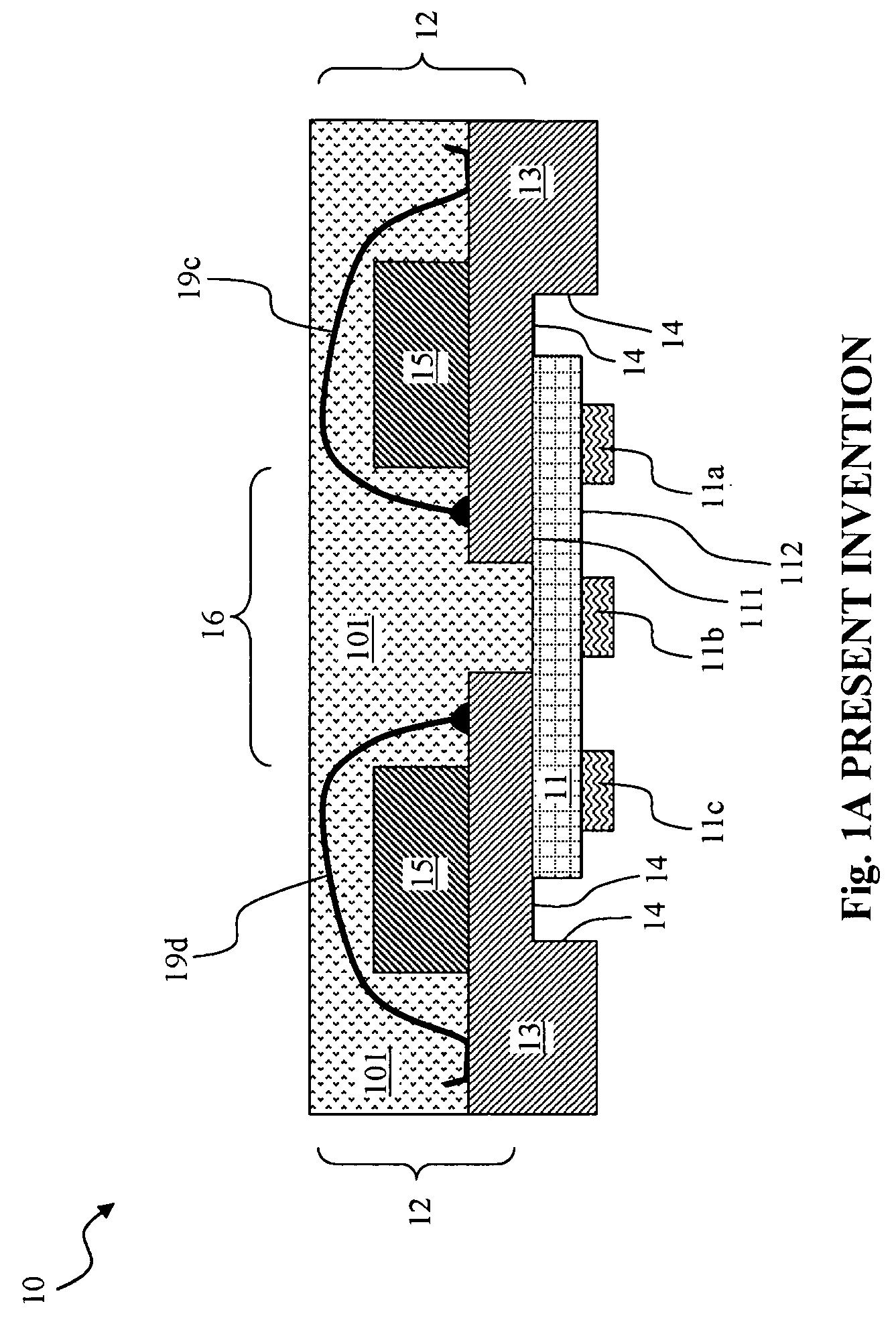
[0060]FIG. 1A through FIG. 1F illustrate the present invention compact power semiconductor package 10 having a bonded stack of power inductor 12, bottom recessed leadframe 13 and power IC die 11 thus exhibiting a reduced package foot print. The bottom recessed leadframe 13 is made, for example by etching, with a bottom recess 14 that should be sized to accommodate the power IC die 11. FIG. 1A is a cross sectional side view of the power semiconductor package 10, FIG. 1B is its top view, FIG. 1C is a top view of an inductor core 15 (e.g., ferrite chip) that is a part of the power inductor 12, FIG. 1D is a top view of bottom half-coil patterned conductive leads 17a through 17g of the bottom recessed leadframe 13, FIG. 1E is a bottom view of the power semiconductor package 10, and FIG. 1F is a bottom view of bottom half-coil patterned conductive leads 17a through 17g mirroring FIG. 1D horizontally.
[0061]The power inductor 12 has a inductor core 15 located atop the bottom recessed leadfr...
third embodiment
[0065]FIG. 3A and FIG. 3B illustrate the bottom views of the present invention using partially sawn leadframes. In the power semiconductor package 30 of FIG. 3A, the bottom recess 14 with partial horizontal sawn edges 31a and 31b can be created by partially sawing the bottom side of a leadframe along a horizontal direction. However, in the power semiconductor package 35 of FIG. 3B, the bottom recess 14 with partial vertical sawn edges 36a and 36b can be created by partially sawing the bottom side of a leadframe along a vertical direction.
fourth embodiment
[0066]FIG. 4A through FIG. 4C illustrate a power semiconductor package 40 using a number of peripheral standoff bumps 43b and 43c at the bottom of leadframe 41 and top half-coil forming interconnection plates 42a through 42h at its top. FIG. 4A is a top view with the encapsulant 101 removed for better visibility of the various internal components. FIG. 4B is the top view of numerous bottom half-coil patterned conductive leads 41a through 41j of leadframe 41. FIG. 4C is a side sectional view of the power semiconductor package 40 along direction A-A.
[0067]Instead of using top half-coil forming bond wires as in FIG. 1A, a number of three dimensionally formed top half-coil forming interconnection plates 42a through 42h, each looping the inductor core 15 from above and further connecting with proper alternative members of the bottom half-coil patterned conductive leads 41a through 41j, are employed to form the inductive coil. Thus, for example, the ends of top half-coil forming interconn...
PUM
| Property | Measurement | Unit |
|---|---|---|
| thickness | aaaaa | aaaaa |
| thickness | aaaaa | aaaaa |
| inductance | aaaaa | aaaaa |
Abstract
Description
Claims
Application Information
 - R&D
- Intellectual Property
- Life Sciences
- Materials
- Tech Scout
- Unparalleled Data Quality
- Higher Quality Content
- 60% Fewer Hallucinations
Browse by: Latest US Patents, China's latest patents, Technical Efficacy Thesaurus, Application Domain, Technology Topic, Popular Technical Reports.
© 2025 PatSnap. All rights reserved.Legal|Privacy policy|Modern Slavery Act Transparency Statement|Sitemap|About US| Contact US: help@patsnap.com


