Remote larger effective area optical fiber

a technology of optical fiber and effective area, applied in the direction of optical elements, electromagnetic repeaters, instruments, etc., can solve the problems of enormous technical challenges in the transmission of optic signals over such long distances, and achieve the effects of reducing optical power density

Active Publication Date: 2011-01-11
NEPTUNE SUBSEA IP LTD
View PDF6 Cites 0 Cited by
  • Summary
  • Abstract
  • Description
  • Claims
  • Application Information

AI Technical Summary

Benefits of technology

[0005]This more remote optical fiber portion is positioned to correspond with a maximum peak optical signal power, but also has a larger effective cross-sectional area than the proximate optical fiber portion in which forward Raman amplification primarily occurs. Accordingly, even though the total optical signal power is higher within the more remote optical fiber portion, the optical power density is reduced due to the larger effective cross-sectional area of the more remote optical fiber portion. The reduction in optical signal power density in the larger effective area fiber results in less information loss due to non-linearity degradation at the peak optical signal power.

Problems solved by technology

Transmission of optic signals over such long distances presents enormous technical challenges.

Method used


Image

  • Remote larger effective area optical fiber
  • Remote larger effective area optical fiber
  • Remote larger effective area optical fiber

Examples


Embodiment Construction

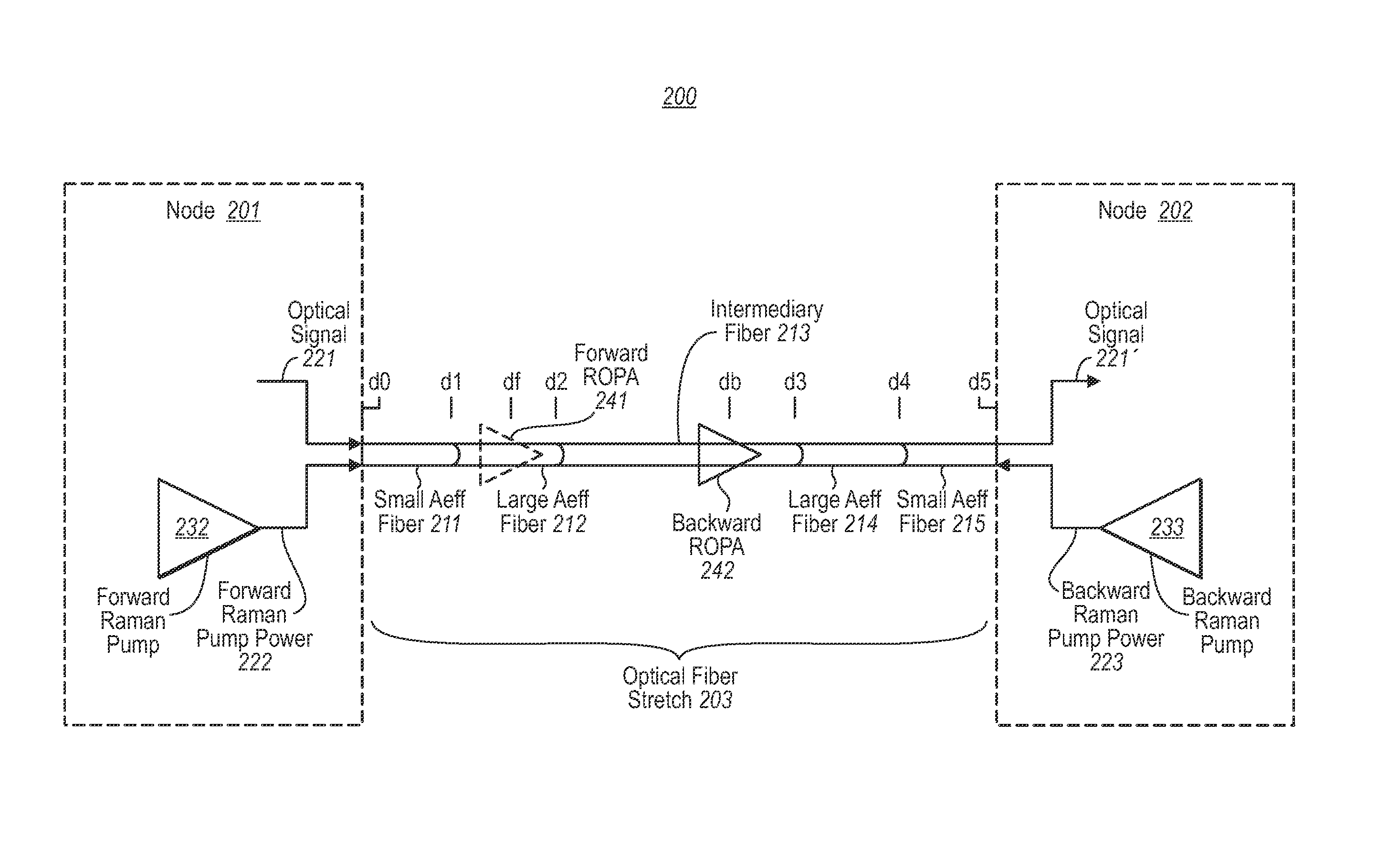
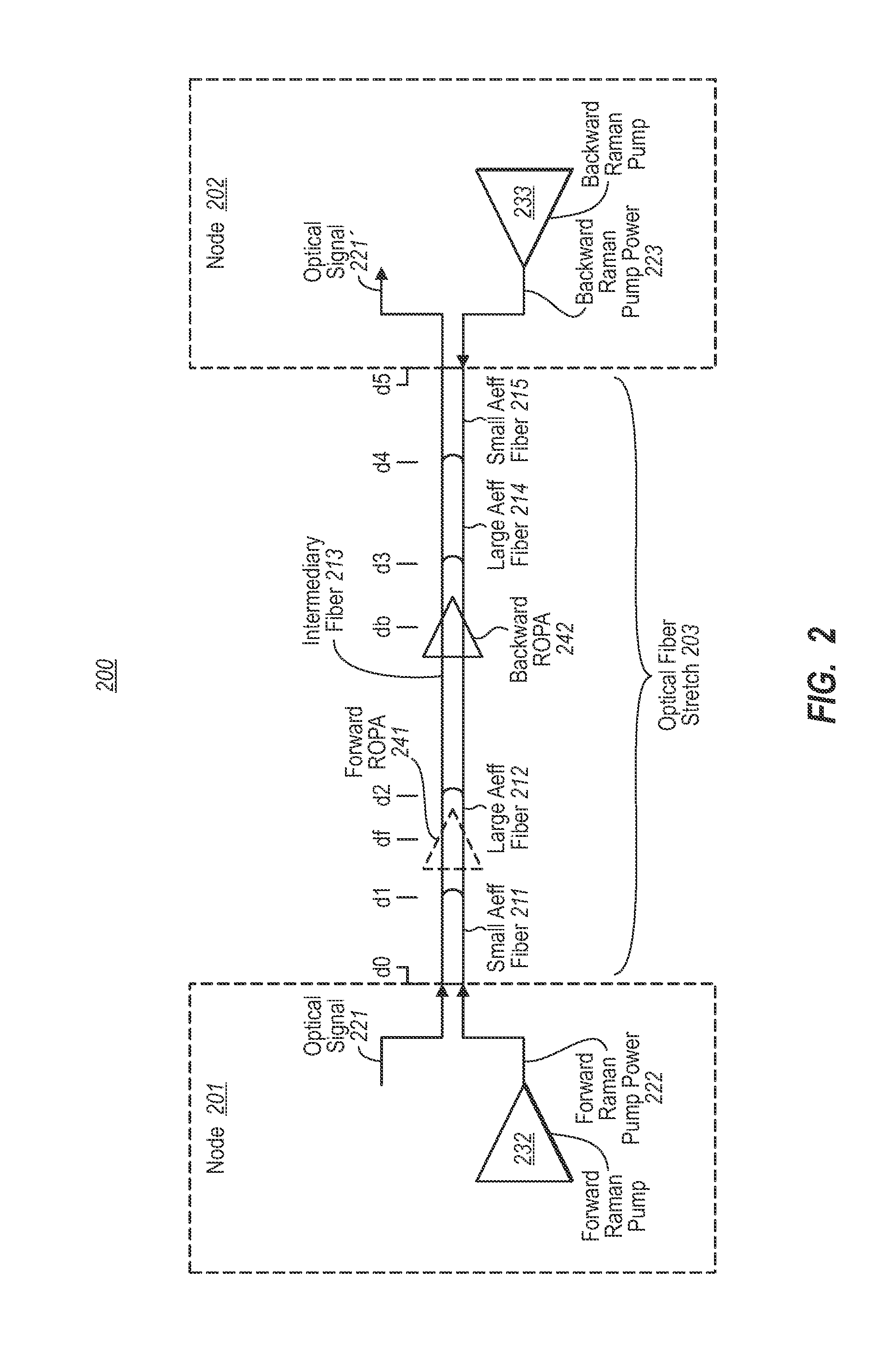
[0012]In accordance with embodiments described herein, an optical fiber stretch may experience forward Raman amplification in which the peak optical signal power occurs at some distance from the transmitter. Smaller effective area optical fiber is used at a portion of the optical fiber stretch in which the optical signal power is increasing due to forward Raman amplification, while larger effective area optical fiber is used at a more remote optical fiber portion that experiences the peak optical signal power. Thus, even though some forward Raman amplification opportunity was lost due to the larger effective area fiber, the quality of the signal is better preserved since the larger effective area fiber reduces maximum optical signal density thereby reducing non-linear degradations on signal quality that are caused by high optical signal density.

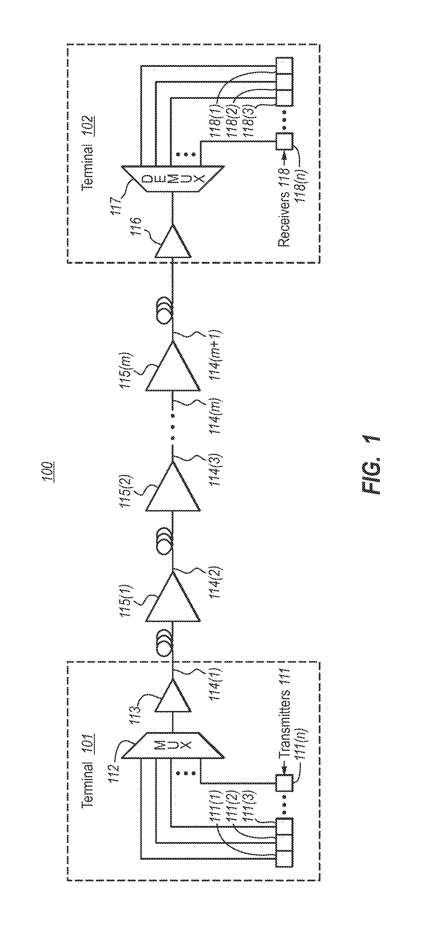
[0013]FIG. 1 schematically illustrates an example optical communications system 100 in which the principles described herein may be employed...


PUM


Abstract

Embodiments described herein relate to an optical fiber stretch that may experience forward Raman amplification in which the peak optical signal power occurs at some distance from the transmitter. Smaller effective area optical fiber is used at a portion of the optical fiber stretch in which the optical signal power is increasing, while larger effective area optical fiber is used at a more remote stretch of the optical fiber stretch that experiences the peak optical signal power. Thus, the quality of the signal is better preserved since the larger effective area fiber reduces maximum optical signal density thereby reducing non-linear degradations on signal quality.

Description

BACKGROUND[0001]Fiber-optic communication networks serve a key demand of the information age by providing high-speed data between network nodes. Fiber optic communication networks include an aggregation of interconnected fiber-optic links. Simply stated, a fiber-optic link involves an optical signal source that emits information in the form of light into an optical fiber. Due to principles of internal reflection, the optical signal propagates through the optical fiber until it is eventually received into an optical signal receiver. If the fiber-optic link is bi-directional, information may be optically communicated in reverse typically using a separate optical fiber.[0002]Fiber-optic links are used in a wide variety of applications, each requiring different lengths of fiber-optic links. For instance, relatively short fiber-optic links may be used to communicate information between a computer and its proximate peripherals, or between local video source (such as a DVD or DVR) and a te...

Claims


Application Information

Patent Timeline
Patent Type & Authority Patents(United States)
IPC IPC(8): G02B6/28H01S3/00H04B10/2581H04B10/29
CPCH04B10/2916H04B10/2543G02B6/02019
Inventor CHANG, DO-ILPUC, ANDREJ B.
Owner NEPTUNE SUBSEA IP LTD
Why Eureka
Try Eureka