Stress monitoring system for railways

a monitoring system and railway technology, applied in the direction of mechanical measuring arrangement, process and machine control, instruments, etc., can solve the problems of temperature-induced failures in rail systems, rail pull-apart and track-buckle failures, and failures of pull-aparts that can easily be detected

Active Publication Date: 2011-01-11
SALIENT SYST
View PDF14 Cites 28 Cited by
  • Summary
  • Abstract
  • Description
  • Claims
  • Application Information

AI Technical Summary

Problems solved by technology

In temperate climates, however, such as those in the United States, Asia, Australia and Europe, the ranges of temperature extremes are sufficient to cause catastrophic, temperature induced failures in rail systems, including both rail pull-apart and track-buckle failures, as hereinafter described.
Fortunately, pull-apart failure can easily be detected by establishing an electrical track circuit using the rails as part of the conduction path, which becomes “open” if one of the rails of the continuous rail track pulls apart.
If the difference between the elevated ambient rail temperature and the RNT is extreme, the compressive stresses in the rails can potentially attain sufficient magnitude to actually cause the track panel to buckle.
Such buckling, previously considered random and unpredictable, is a major source of derailments.
As a result, track-buckle poses a substantially greater risk of derailment than does a rail pull-apart since the former cannot be detected by a conventional track circuit.
Although various methods, systems and apparatus have been developed to measure and / or determine longitudinal stresses in a rail of a continuous rail track, none of them have been used to accurately determine whether a section of continuous rail track is within specific safety limits.

Method used


Image

  • Stress monitoring system for railways
  • Stress monitoring system for railways
  • Stress monitoring system for railways

Examples


Embodiment Construction

[0028]Exemplary embodiments of the present invention are now described with reference to the Figures. Reference numerals are used throughout the detailed description to refer to the various elements and structures. For purposes of explanation, numerous specific details are set forth in the detailed description to facilitate a thorough understanding of this invention. It should be understood, however, that the present invention may be practiced without these specific details. In other instances, well-known structures and devices are shown in block diagram form for purposes of simplifying the description.

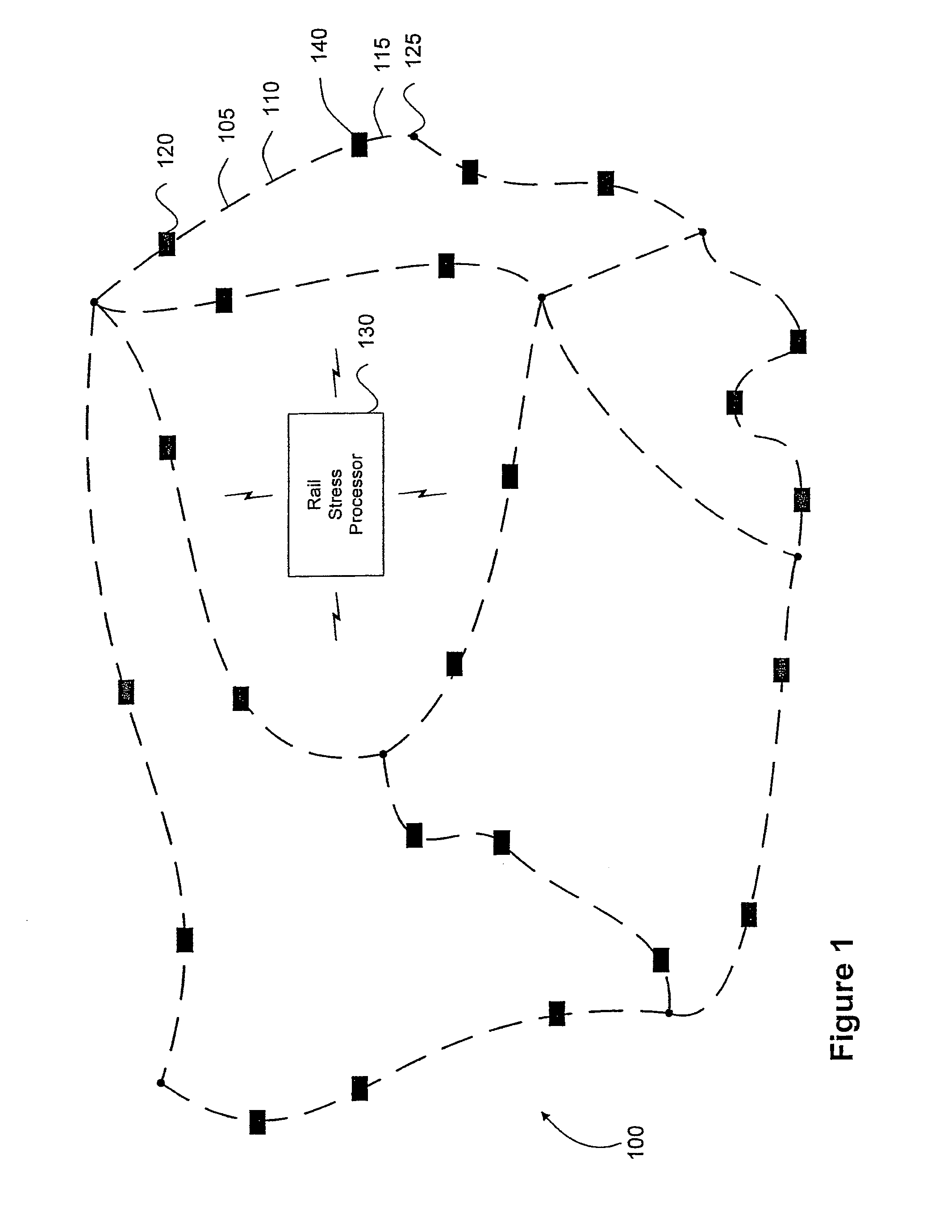
[0029]Referring to FIG. 1, a schematic diagram illustrates an example network 100 of continuous rail track. The illustrated continuous welded rail track network 100 includes a plurality of CWR track portions, such as rail portions 105, 110, and 115, for example. The CWR track portions create paths between certain nodes, such as the path between nodes 120 and 125. Certain of CWR track ...


PUM

PropertyMeasurementUnit
lengthaaaaaaaaaa
lengthaaaaaaaaaa
lengthaaaaaaaaaa

Abstract

A rail stress monitoring system is disclosed. This system includes a sensor module that further includes a sensing device that is adapted to be mountable directly on a length of rail. The sensing device further includes a generally flat metal shim and at least one, and typically two or more, sensors mounted on one side of the shim. The sensors are typically strain gauges, which are mounted on the shim in a specific, predetermined configuration. At least one data acquisition module is in electrical communication with the sensing device and a data processing module receives and processes information gathered by data acquisition module.

Description

CROSS-REFERENCE TO RELATED APPLICATIONS[0001]This patent application is a continuation-in-part of U.S. patent application Ser. No. 10 / 899,265 filed on Jul. 26, 2004 and entitled “System and Method for Determining Rail Safety Limits”.TECHNICAL FIELD OF THE INVENTION[0002]The described systems and methods are generally related to information processing environments for monitoring longitudinal stresses in continuously welded steel rails (“CWR”). More specifically, the described systems and methods are related to processing monitored stress levels to determine limits of rail safety.BACKGROUND OF THE INVENTION[0003]Over the last forty years, an effort has been underway to eliminate the mechanical joints in railroad tracks. That effort has largely involved constructing tracks having continuous rails by welding or otherwise joining together the ends of the adjacently spaced rail sections, forming a structure sometimes referred to as continuous welded rail track. The technology associated w...

Claims


Application Information

Patent Timeline
Patent Type & Authority Patents(United States)
IPC IPC(8): G01L1/04G01B7/16G01L1/00G06F17/00
CPCB61K9/08B61L23/044B61L23/047B61L23/048B61L27/0088B61L27/53
Inventor HARRISON, HAROLD
Owner SALIENT SYST
Why Eureka
Try Eureka