Microwave humidifier

Inactive Publication Date: 2011-01-18
COMFORT SPECIALISTS
View PDF12 Cites 4 Cited by
  • Summary
  • Abstract
  • Description
  • Claims
  • Application Information

AI Technical Summary

Benefits of technology

[0006]In accordance with the purpose of the present invention broadly described herein, one embodiment of this invention comprises an air humidifier system. The system comprises a water reservoir and means for heating water in the reservoir using microwave energy. The reservoir may comprise a cavity that can contain microwave energy therewithin, and the means for heating water may be a magnetron positioned near the reservoir. Alternatively, the means for heating water may comprise a cavity surrounding the water reservoir, with the cavity able to contain microwave energy therewithin. The reservoir may be easily removable from and replaceable into the system, thereby facilitating cleaning.

Problems solved by technology

Such dry air can cause skin and mucous membranes to dry out, making people uncomfortable and perhaps increasing their susceptibility to infection by air-borne viruses and bacteria.
Dry air can also lead to drying of wood structures, such as flooring and furniture, and it can lead to increased static electricity that may damage electronic equipment, such as computers.
These types of systems generally require significant maintenance to prevent scale buildup on the pads or sheets or in the nozzles.
As a result, the humidifier becomes increasingly inefficient.
Although frequently flushing clean water through the tank can slow down the rate of scale buildup, there is no simple way to remove the scale deposits once they form in the tanks and in associated plumbing, and the tanks must be replaced periodically.

Method used


Image

  • Microwave humidifier
  • Microwave humidifier
  • Microwave humidifier

Examples


Embodiment Construction

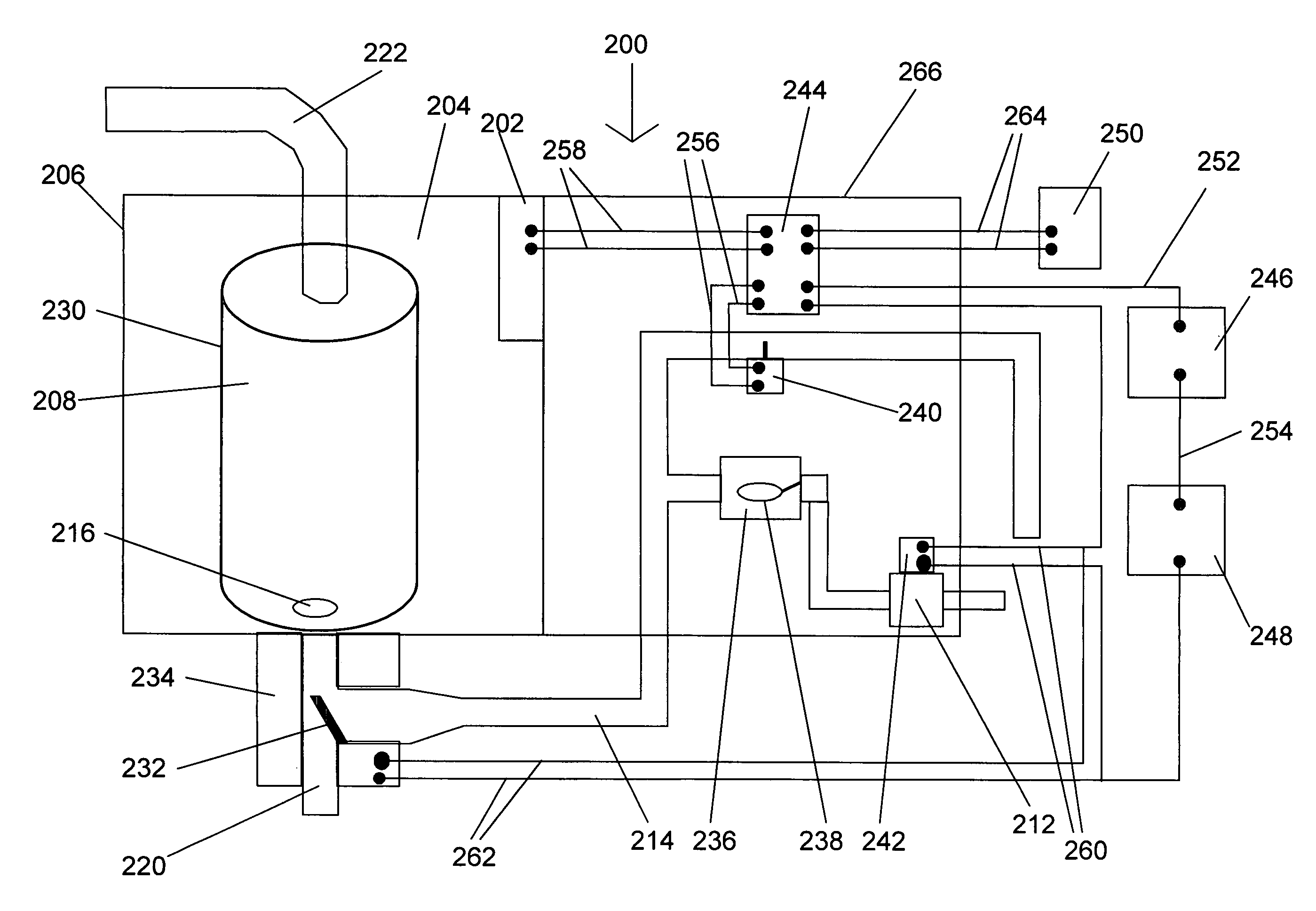
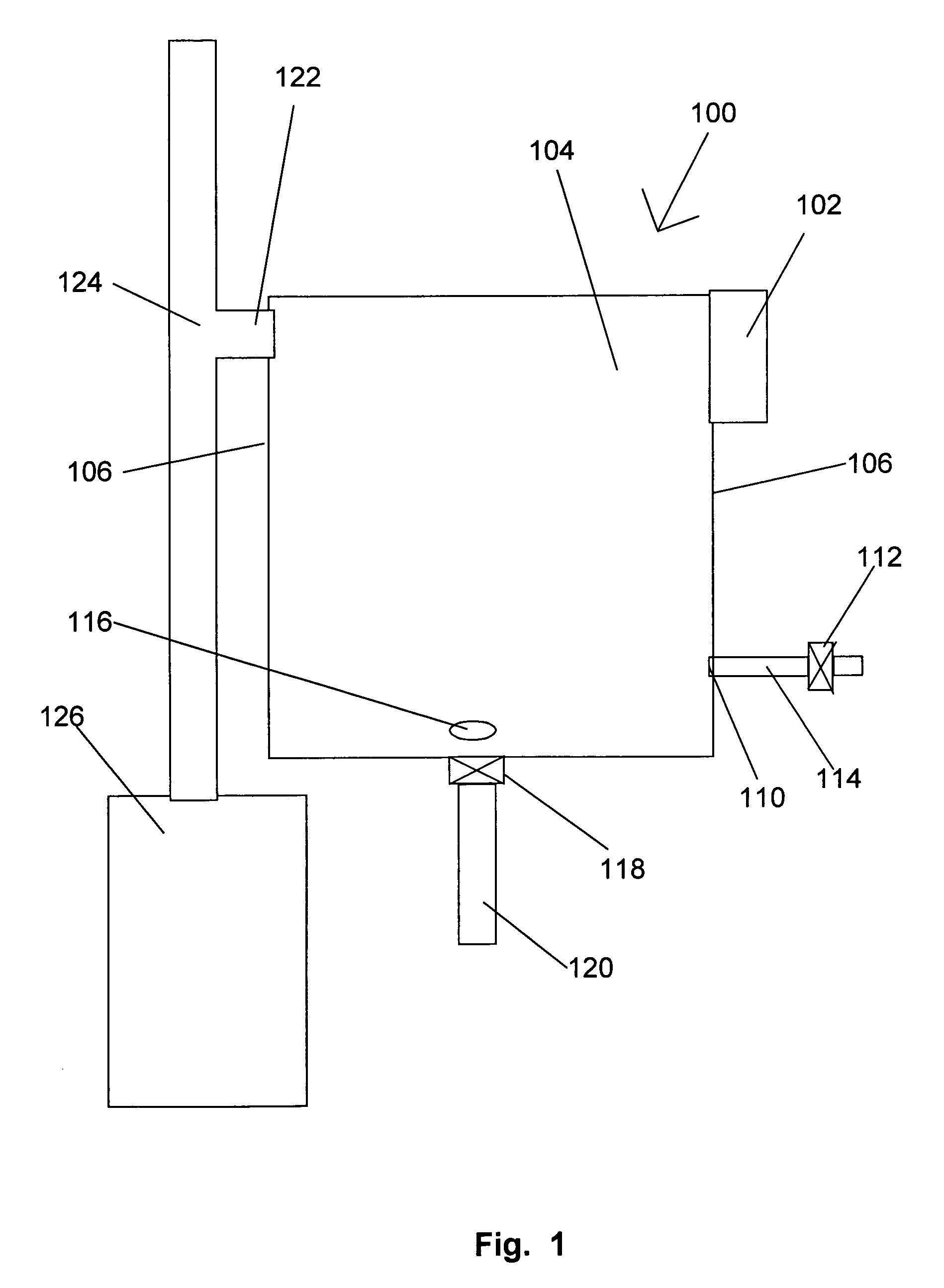
[0016]In accordance with the present invention, microwave energy can be used to evaporate water inside a reservoir and supply humidity to air.

[0017]One embodiment of a microwave humidifier system 100 in accordance with the present invention in shown in FIG. 1. A magnetron or other microwave source 102 is adjacent microwave cavity / reservoir 104, similar to a conventional microwave oven. Preferably, cavity / reservoir 104 has walls 106 that are appropriately shielded to prevent leakage of microwaves outside of cavity 104. Cavity / reservoir 104 has a water inlet 110, equipped with inlet valve 112 in inlet conduit 114, and a drain 116, equipped with drain valve 118 in outlet conduit 120. A steam outlet 122 is provided generally near the top of reservoir 108 for escape of steam from the reservoir and into an air duct 124 in a forced air heating system, delivering air from furnace 126 to a room. Alternatively, the steam can be released directly into a room. If the steam is released directly ...


PUM

PropertyMeasurementUnit
Flow rateaaaaaaaaaa
Energyaaaaaaaaaa

Abstract

Air humidification system using microwave energy to heat water to produce steam. The system may include an automatic controller.

Description

FIELD OF THE INVENTION[0001]The present invention relates generally to an apparatus and method for humidifying air, and more specifically to an apparatus and method that use microwave energy to generate steam for humidifying air.BACKGROUND OF THE INVENTION[0002]When using a heating system to provide ambient air at a comfortable temperature indoors, it is often desirable to increase the humidity of the heated air. If the air to be heated is initially very cold, such as outdoor air in winter, the heated air will contain very little moisture. Indeed, indoor air may have a humidity, or moisture content, as low as 10 to 15 percent, which is significantly drier than even desert air. Such dry air can cause skin and mucous membranes to dry out, making people uncomfortable and perhaps increasing their susceptibility to infection by air-borne viruses and bacteria. Dry air can also lead to drying of wood structures, such as flooring and furniture, and it can lead to increased static electricit...

Claims


Application Information

Patent Timeline
IPC IPC(8): B01F3/04
CPCF22B1/284F24F6/18Y10S261/15
Inventor MONTREUIL, MICHAELBLASHAW, SCOTT
Owner COMFORT SPECIALISTS
Why Eureka
Try Eureka