Laser engagement stun system

a technology of laser tag and snare, which is applied in the direction of optical radiation measurement, instruments, target detectors, etc., can solve the problems of inferior laser tag system and limited function of devices, and achieve the effect of easy recognition

Active Publication Date: 2011-01-18
ELLIOTT JR JOHN BERNARD
View PDF3 Cites 15 Cited by
  • Summary
  • Abstract
  • Description
  • Claims
  • Application Information

AI Technical Summary

Benefits of technology

[0011]An object of the present invention is to provide military and other personnel in a Hostile engagement situation to use more caution to prevent their being Wounded or Killed in Action KIA and allow them to more readily recognize situation that might put them or their fellow comrade in Arms in harms way.) This new device that will be used for training exercises will take training and realism to a new level not experienced in the prior art.

Problems solved by technology

These devices are limited in their function, 47) U.S. Pat. No. 4,695,058t describes a laser tag system is inferior because the laser stun engagement system can accomplish all the tasks the laser tag system can perform and do the following tasks that the laser tag system cannot do, LESS can send a tactile electrical shock notification to the person wearing the man worn vest, LESS is self charging from ambient light during use and between being used thereby extending time in the field for the person wearing the vest.

Method used


Image

  • Laser engagement stun system
  • Laser engagement stun system
  • Laser engagement stun system

Examples


Embodiment Construction

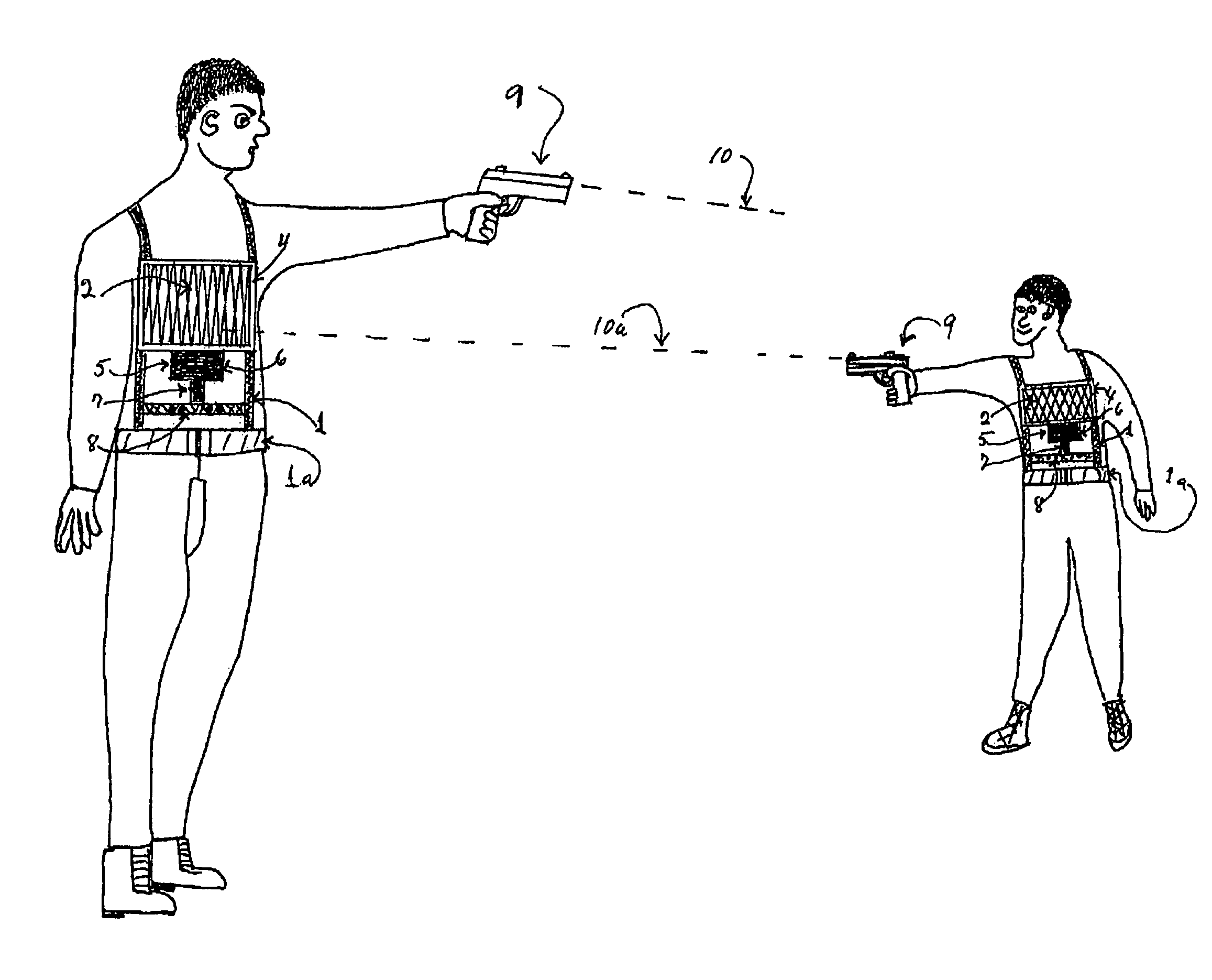
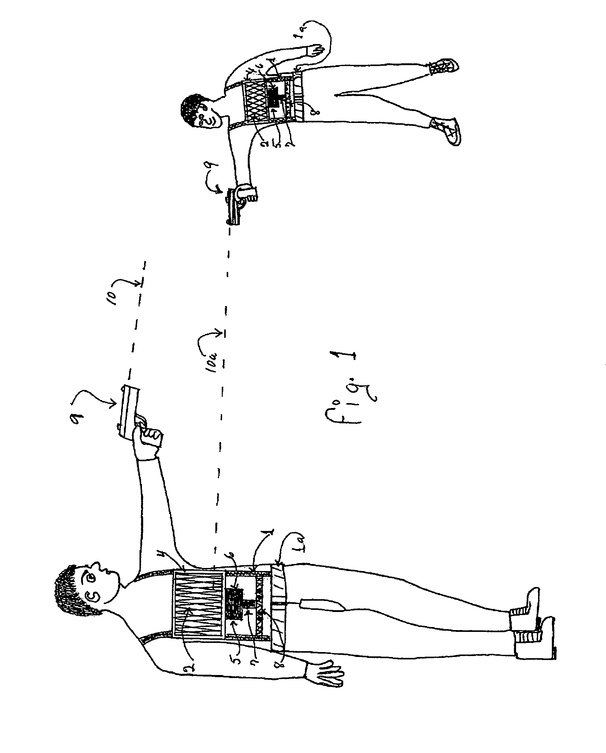
[0027]The laser engagement stun system according to the illustrated embodiment includes a laser device arranged to generate a coded pulse laser comprising light in the form of a coded pulse and a man worn apparatus arranged to be worn by a user and being separate from the laser device.

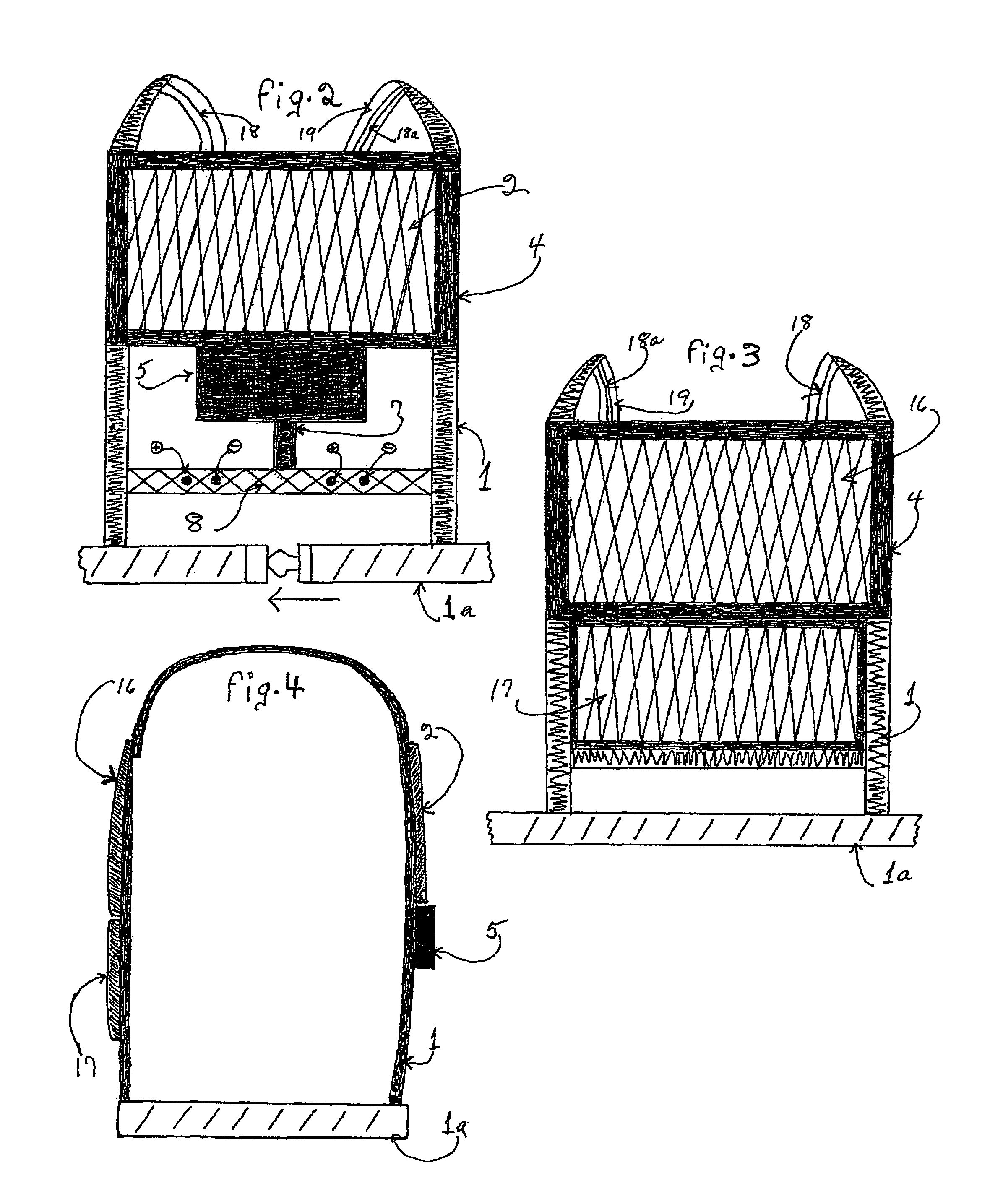
[0028]The man worn apparatus includes electrical contacts supported on the apparatus so as to be arranged to deliver a high voltage stun to a user of the apparatus. A solar cell is also supported on the apparatus in which the solar cell is arranged to generate a coded signal in response to being electrically charged by the coded pulse laser from the laser device.

[0029]An electronic circuit board is also supported on the apparatus in which the electronic circuit board is arranged to detect the coded signal from the solar cell such that the electronic circuit board can discriminate between ambient light and the coded pulse laser, and the electronic circuit board being arranged to convert the coded signal...


PUM


Abstract

The Laser Engagement Stun System, which is a man Worn Apparatus is designed for Training exercises in Force-on Force or One-on-One training. The L.E.S.S. system receives and analyzes incoming laser light signals while disregarding ambient light signals from the environment. It then generates a High Voltage low amperage pulsed shock or stun that is delivered to the person wearing the LESS. Each person in the exercises will be equipped with the Laser Engagement Stun System. A component and vital part of the system is the weapons mounted Visible Laser Light device attached to each persons weapon. The attached laser light device will be activated when the individual person pulls the trigger on their weapon and cause a Blank Round to be discharged or from a Dry Fire. When the person so equipped as described above with LESS, and weapons mounted Laser Light device, the person may aim his weapon at the opponent and shoot a blank or dry fire and if the aim was true and the laser light strikes the Sensor on the LESS, the person wearing the LESS will feel a mild electrical shock or stun to simulate a bullet hitting that person. Realism during training has become more and more valuable in preventing lives being lost, wounds and other injuries from being sustained because of the lack of realism during training. Only a system wherein the person experiencing the Tactile notification of being hit by a bullet and killed or wounded can prevent the possibility of that reality. Laser Engagement Stun System can address the Age Old problem of FRATRICIDE OR FRIENDLY FIRE. A back Sensor panel and rear helmet Sensor can detect and stun a friendly in a special location that can be immediately identified as FRIENDLY FIRE.

Description

BACKGROUND OF THE INVENTION[0001]This invention relates generally to the field of apparatus for a FORCE-ON FORCE Training system. Moreover it pertains specifically to such apparatus for Force-on Force Training where Realism is a key part of imparting the importance of the Lesson of the Day i.e. DON'T GET KILLED. The age old problem of training Soldiers for the field or Police Officers for Hostile Engagements in the line of duty has been and will always be one of the most intense and concentrated efforts during the training period one will receive when their job requirement demands the very best performance. Hell Week that our Navy Seals receive gives one the idea of what it really takes to be the very best. Because of time and money restrictions and the need to impart the best training to as many as possible in the shortest amount of time, Realistic training is now being extended from Elite Force to the line soldier or line officer and other security personnel. Simulations of all ki...

Claims


Application Information

Patent Timeline
Patent Type & Authority Patents(United States)
IPC IPC(8): H01T23/00
CPCF41A33/02F41G3/2627F41G3/2655F41J5/02G01J1/42
Inventor ELLIOTT, JR., JOHN BERNARD
Owner ELLIOTT JR JOHN BERNARD
Why Eureka
Try Eureka