Storage controller and data erasing method for storage device

a storage controller and data technology, applied in the field of storage controller and data erasing method for storage devices, can solve the problems of hardly continuously erased data, deteriorating user maneuverability, and longer time required for erasing data, so as to reduce the size of erasing data and reduce stepwise

Inactive Publication Date: 2011-01-18
HITACHI LTD
View PDF12 Cites 8 Cited by
  • Summary
  • Abstract
  • Description
  • Claims
  • Application Information

AI Technical Summary

Benefits of technology

[0010]The present invention is devised by considering the above-described problems and it is an object of the present invention to provide a storage controller and a data erasing method for a storage device that manage a state of the progress of a data erasing process or a data shredding process and can re-execute the data erasing process of an incomplete storage area where data cannot be erased due to an error.
[0011]It is another object of the present invention to provide a storage controller and a data erasing method in which a data erasing process is carried out in an initial size until an error arises, and the data erasing process is carried out again in a small size after the error arises so that the data erasing process can be carried out in a relatively short time and a range of data to be erased can be increased.
[0018]The data erasing part can repeatedly re-execute the data erasing process by reducing the size of the erasing data from the initial value to the minimum value until the data erasing process of the incomplete storage area is completed after the data erasing part carries out the data erasing process of all the storage areas by using the erasing data of the initial size.
[0021]The data size setting part can reduce the size of the erasing data stepwise within a designated range.
[0022]The data size setting part can reduce stepwise the size of the erasing data ¼ times at a time from the initial value.

Problems solved by technology

However, as the capacity of the storage device is more increased, a time necessary for erasing the data is the longer, the maneuverability for users is deteriorated.
Further, in the existing technique, since a state of the progress of an erasing operation of the data is not managed, when a write error occurs during the erasing operation of the data, the data is hardly continuously erased.

Method used


Image

  • Storage controller and data erasing method for storage device
  • Storage controller and data erasing method for storage device
  • Storage controller and data erasing method for storage device

Examples


first embodiment

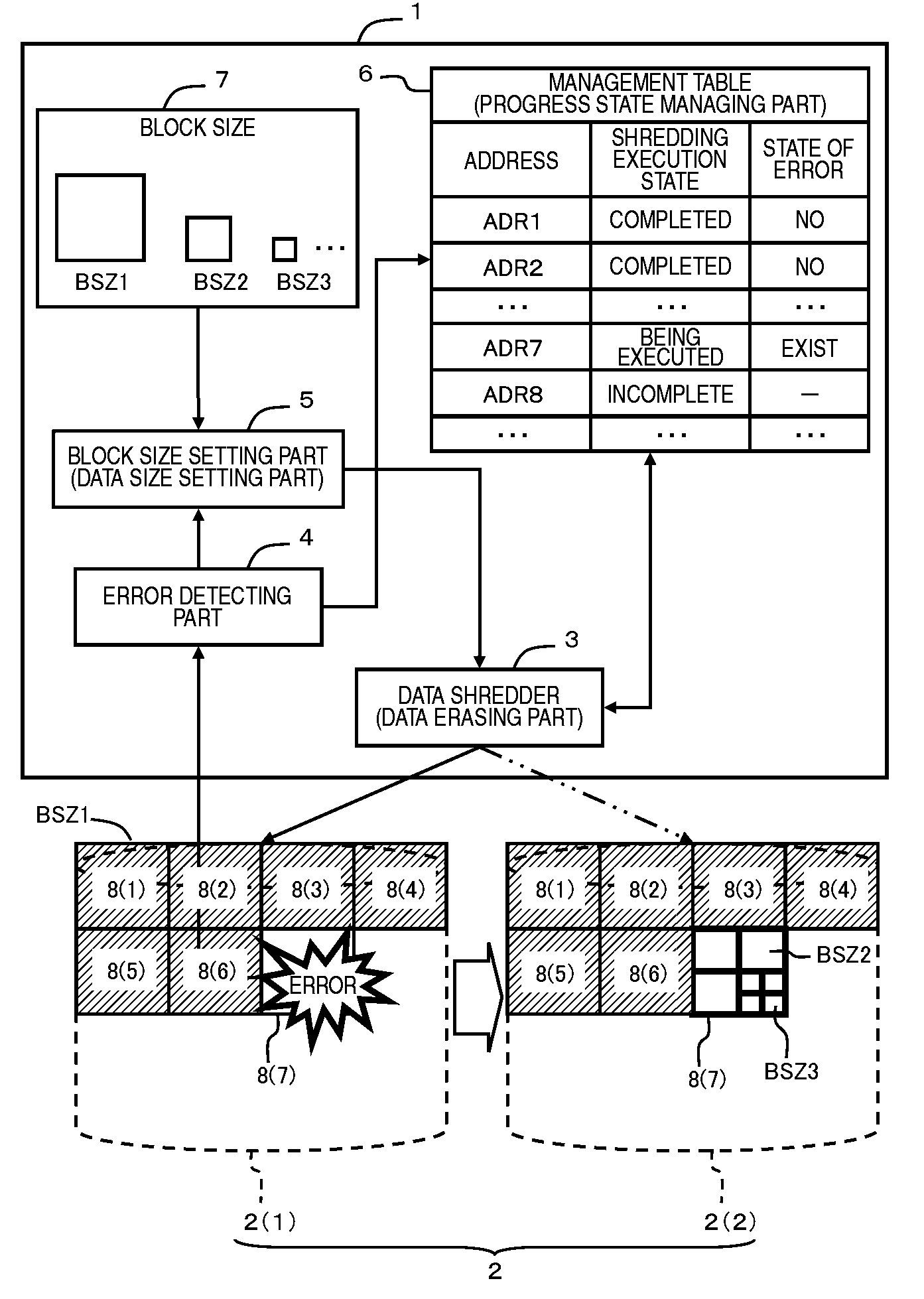
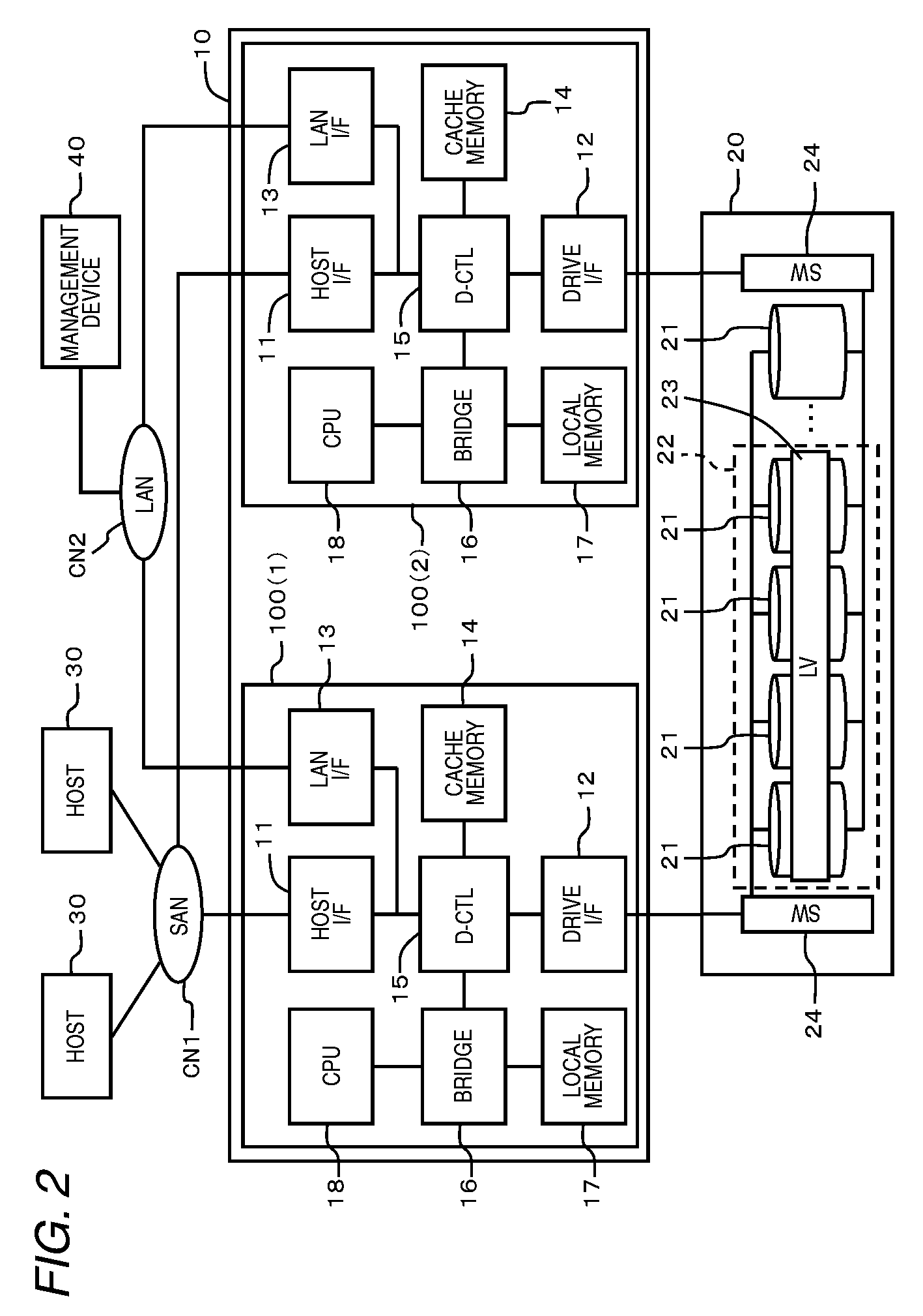
[0070]FIG. 2 is an explanatory view showing an entire structure of the storage system according to this embodiment. The storage system includes, for instance, a basic chassis 10, an increased chassis 20, a host 30 and a management device 40. The host 30 is connected to the basic chassis 10 by a communication network CN1 such as FC-SAN (Fibre Channel-Storage Area Network) or IP-SAN (Internet Protocol-SAN). The management device 40 is connected to the basic chassis 10 by a communication network CN2 such as LAN (local Area Network).

[0071]A corresponding relation of FIG. 2 to FIG. 1 will be described beforehand. A controller 100 corresponds to the controller 1 shown in FIG. 1. A disk drive 21 corresponds to the disk drive 2 in FIG. 1. A CPU 18 in the basic chassis 10 reads a prescribed program and executes the program so that the functions of the data shredder 3, the error detecting part 4 and block size setting part 5 described in FIG. 1 are realized.

[0072]Other structures than the str...

second embodiment

[0214]Now, referring to FIGS. 28 and 29, a second embodiment of the present invention will be described below. This embodiment corresponds to a modified embodiment of the first embodiment. In this embodiment, a basic chassis 10 carries out a shredding process of data stored in another basic chassis 10E provided in an external part of the basis chassis 10.

[0215]FIG. 28 shows an entire structure of a storage system according to this embodiment. In this system, a plurality of basic chassis 10 and 10E are included. The basic chassis 10 and another basis chassis 10E are respectively provided in separate places.

[0216]An initiator port provided in a host interface 11 of the basic chassis 10 is connected to a target port provided in a host interface 11 of another basic chassis 10E through a communication network CN1.

[0217]Another basic chassis 10E is connected to an increased chassis 20E. A controller 100E of another basic chassis 10E controls an input and output of data to a logical volume...


PUM


Abstract

A storage controller changes a block size to carry out a shredding process. A data shredder uses a large block size set by a block size setting part to write shredding data in a storage area of a disk drive and erase data stored therein. An error arising during the writing operation of the shredding data is detected by an error detecting part. When the error is detected, the block size setting part sets the block size smaller by one stage than the initial block size to the data shredder. Every time the error arises, the block size used in the shredding process is diminished. Thus, the number of times of writings of the shredding data is reduced as much as possible to improve a processing speed and erase the data of a wide range as much as possible.

Description

CROSS REFERENCES TO RELATED APPLICATIONS[0001]This application relates to and claims priority from Japanese Patent Application No. 2008-240316, filed on Sep. 19, 2008, the entire disclosure of which is incorporated herein by reference.BACKGROUND OF THE INVENTION[0002]1. Field of the Invention[0003]The present invention relates to a storage controller and a data erasing method for a storage device.[0004]2. Description of the Related Art[0005]For instance, a host computer (refer it to as a “host”, hereinafter) such as a server computer or a main frame computer manages data by using a storage controller. The storage controller is also called RAID (Redundant Array of Inexpensive Disks) system and can provide a redundant storage area to the host.[0006]Since the data to be managed is increased year by year, the capacity of the storage is desired to be enlarged. On the other hand, as the capacity of the storage device is more increased, a data erasing time is the longer when the storage de...

Claims


Application Information

Patent Timeline
Patent Type & Authority Patents(United States)
IPC IPC(8): G06F11/00
CPCG06F11/1435
Inventor OHARA, MAO
Owner HITACHI LTD
Why Eureka
Try Eureka