Liquid transporting apparatus and ink-jet printer

a technology which is applied in the field of liquid transporting apparatus and inkjet printer, can solve the problems of increasing an overall cost and being unable to make the heater generate heat, and achieve the effect of constant viscosity of ink and stable jetting of ink

Active Publication Date: 2011-01-25
BROTHER KOGYO KK
View PDF7 Cites 2 Cited by
  • Summary
  • Abstract
  • Description
  • Claims
  • Application Information

AI Technical Summary

Benefits of technology

The present invention is made in view of the abovementioned circumstances, and an object of the present invention is to improve a degree of freedom of an operation timing of the heater, and to improve a heating efficiency of an ink (liquid).
In the present invention, the liquid transporting apparatus may further include a temperature sensor; and the controller may control the heater based on a temperature measured by the temperature sensor. In this case, by controlling the heater according the temperature measured by the temperature sensor, it is possible to maintain the temperature of ink to be constant. Therefore, the ink-jet printer of the present invention is capable of maintaining a viscosity of the ink to be constant, and is capable of jetting the ink stably.

Problems solved by technology

When the drive voltage of the piezoelectric actuator is increased, electrical components which can withstand high voltage are to be used as electrical components which are connected to the ink-jet head, and this leads to an increase in an overall cost.
Therefore, it is not possible to make the heater generate heat simultaneously with driving of the piezoelectric actuator for which it is necessary to keep an electric potential of the common electrode zero.

Method used


Image

  • Liquid transporting apparatus and ink-jet printer
  • Liquid transporting apparatus and ink-jet printer
  • Liquid transporting apparatus and ink-jet printer

Examples


Embodiment Construction

Embodiments of the present invention will be described below by referring to the accompanying diagrams.

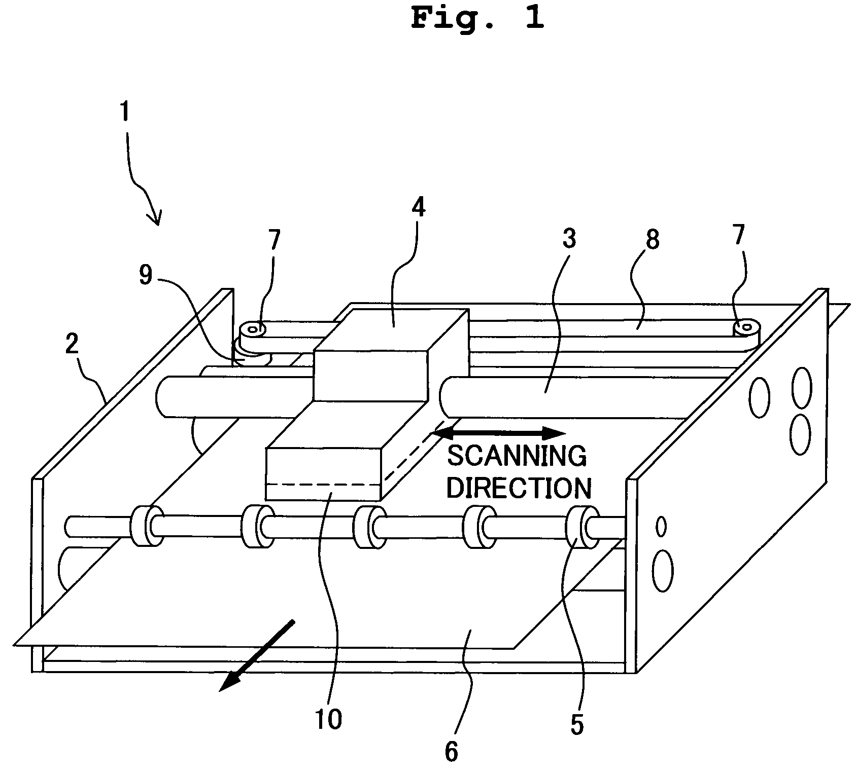
FIG. 1 is a schematic perspective view of an ink-jet printer 1 according to a first embodiment of the present invention. As shown in FIG. 1, the ink-jet printer 1 includes a guide rod 3 installed in a housing 2, and a carriage 4 is slidably supported by the guide rod 3. An ink-jet head 10 (liquid transporting apparatus) is provided at a lower portion of the carriage 4, and an ink is jetted from the ink-jet head 10 toward a recording paper 6 which is transported by paper feeding rollers 5, under the ink-jet head 10. The carriage 4 is joined to a timing belt which is put around a pair of pulleys 7, and the timing belt is arranged parallel to an axial direction of the guide rod 3. A motor 9 which is driven to perform reciprocal rotation (normal and reverse rotation) is provided on one of the pulleys 7, the timing belt 8 is reciprocated by the pulley 7 being driven to perform reciproca...


PUM


Abstract

A liquid transporting apparatus includes a channel unit in which a plurality of pressure chambers are provided, and a piezoelectric actuator which changes individually a volume of each of the pressure chambers. The piezoelectric actuator includes a vibration plate, a piezoelectric body provided on one surface of the vibration plate, and electrodes which apply an electric voltage to the piezoelectric body. The other surface of the vibration plate is joined to the channel unit to close openings of the pressure chambers, and the one surface of the vibration plate includes an uncovered area which is not covered with the piezoelectric body. Since a heater is provided in the uncovered area, and an electrode for applying an electric current is provided separately from the electrodes of the piezoelectric actuator, it is possible to operate the heater even when the piezoelectric actuator is being driven.

Description

CROSS-REFERENCE TO RELATED APPLICATIONThe present application claims priority from Japanese Patent Application No. 2006-211174, filed on Aug. 2, 2006, the disclosure of which are incorporated herein by reference in its entirety.BACKGROUND OF THE INVENTION1. Field of the InventionThe present invention relates to a liquid transporting apparatus which transports a liquid from a liquid supply port up to a plurality of liquid jetting ports, and an ink-jet printer.2. Description of the Related ArtAn ink-jet head which transports an ink supplied from an ink tank, and jets ink droplets from nozzles to a recording paper or the like has already been known. Ink-jetting methods are classified according to a difference in a method for generating jetting energy. There are ink-jetting methods such as a piezo method in which ink droplets are jetted by using a vibration force of a piezoelectric element, and a Bubble Jet® method in which ink droplets are jetted by generation of air bubbles by heat en...

Claims


Application Information

Patent Timeline
Patent Type & Authority Patents(United States)
IPC IPC(8): B41J2/045
CPCB41J2/14016B41J2/14233
Inventor SUGAHARA, HIROTO
Owner BROTHER KOGYO KK
Why Eureka
Try Eureka