
Probe card repair using coupons with spring contacts and separate atachment points

a technology of probe card and spring contact, which is applied in the direction of resistive material coating, printed circuit assembling, metallic material coating process, etc., can solve the problems of significant increase in the bandwidth of an integrated circuit, limitations become even more severe, and most probe card technologies cannot replicate the high frequency environment of high bandwidth ics, etc., to achieve better impedance control, short springs, and improved power/ground distribution

Inactive Publication Date: 2011-01-25
INNOCONNEX
View PDF29 Cites 14 Cited by
  • Summary
  • Abstract
  • Description
  • Claims
  • Application Information

AI Technical Summary

Benefits of technology

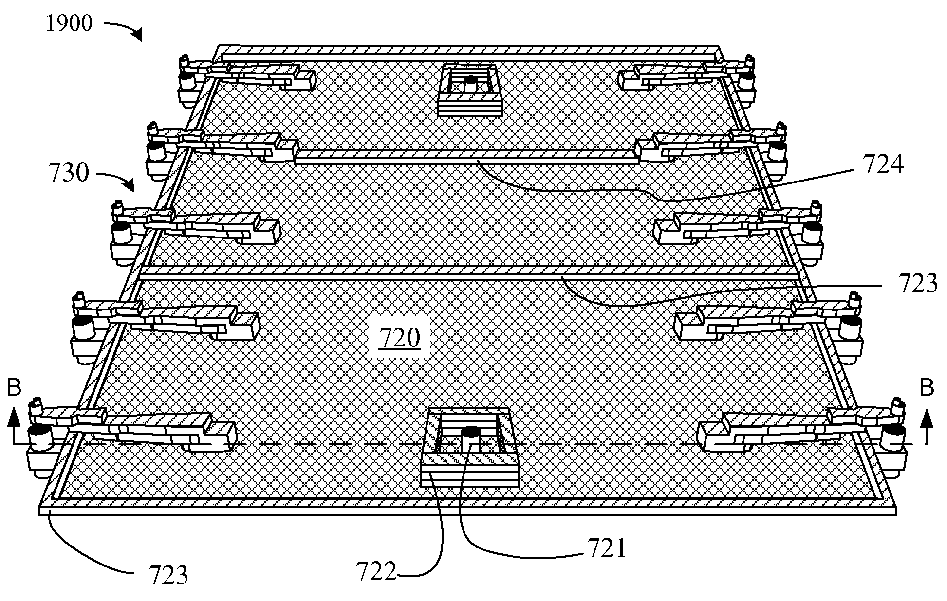
[0024]Several embodiments of the invention provide probecard architectures that enable partitioning the spring compliance required for ICs testing between several different components in the probecard. Such architectures can provide shorter springs, better impedance control, improved power / ground distribution and more direct paths to tester electronics. The architecture can also reduce the cycle time required to manufacture the probecard and enables fabricating both simpler MEMS probes and HDI substrates which results in a lower probecard manufacturing cost.
[0025]In one specific embodiment of the invention, a probecard includes an interconnector substrate, a first spring network, and a second spring network. The first spring network, which provides an interface for making electrical contacts to pads of a device being tested electrically, is connected at a first surface of the interconnector substrate to traces in the interconnector substrate. The second spring network is on a second surface of the interconnector substrate and provides an interface to a tester. The first spring network and the second spring network allow the interconnect substrate to float (instead of being rigidly held) while the probecard is contacting a device being tested.

Problems solved by technology

High frequency operation with a large number of pads significantly increases the bandwidth of an integrated circuit.
Due to electrical limitations, most probecard technologies cannot replicate the high frequency environment that high bandwidth ICs require.
These limitations become even more severe as the frequency and number of signals on an IC increase.
As a result, traditional techniques for building probecards cannot meet these performance demands.
The result of testing with traditional techniques can be the rejection of some good ICs that testing falsely classifies as bad units.
Also, the cost of testing ICs has been rapidly growing as a percentage of the total costs to manufacture ICs.
The increasing number of transistors, number of pads and higher frequency operation increases the tester costs and time needed to test ICs.
Even at lower frequencies (<100 MHz), high inductance probes have more electrical noise which results in lower test yield (i.e., good ICs are categorized as bad devices).
The manufacturing process needed to align these probes to the pads on an IC is a manual mechanical placement technique which becomes increasingly difficult to perform as the spacing of the electrical pads become closer together.
In most applications, these probes are too long to escape all the signals on a single IC in the space of the IC.
This means for full wafer testing their use is restricted to very low pin density applications such as NAND Flash ICs that have relatively large die size with low pin counts or BIST (Built in Self Test) circuits that have fewer than 12 pins per IC.
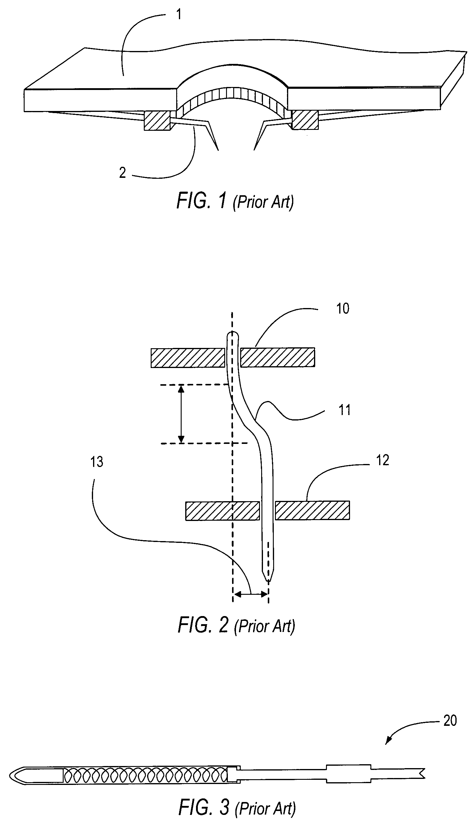
If the cantilever spring is damaged during probing, the repair process generally produces a less reliable probe.
Cantilever probes cannot scale to meet the needs of testing at higher frequencies when migrating to a finer pad pitch.
This means that cantilever probes have limited applications for simultaneously contacting all of the pads on a single wafer.
Also, as IC pad pitch shrinks, the frequency performance of these approaches is reduced.
Smaller springs needed for tighter pad pitches are usually more expensive.
The above mentioned vertical spring approaches cannot meet the performance or cost needs of IC testing as ICs continue to scale to tighter pitches, higher pin counts and larger probing areas.
The resistance of long narrow traces will not meet the requirements for testing a full wafer of memory ICs.
Using more routing layers makes the membrane rigid and it is no longer flexible enough to provide enough compliance to accommodate the planarity differences between the IC wafer and the probecard PCB.
As the size of the manufacturing format grows, the dimensional stability of the membrane is not adequate to stay aligned to the IC pads needed for testing 200 mm or 300 mm wafers.
Larger formats also become prohibitively expensive.
Even in single IC testing applications, if a membrane is damaged, the entire membrane must be replaced which is a large expense.
They are difficult to replace, and repair is limited to springs that are easily accessible near the perimeter of the array of springs.
Although traditional vertical or buckling beam probes can escape within a DRAM die array, they became prohibitively expensive as these probes need to shrink in size when over 10,000 vertical probes are needed to make contact to fine pad pitches of DRAM devices.
Repair is very difficult at the customer's manufacturing line and repair is typically limited to springs near the perimeter of an array.
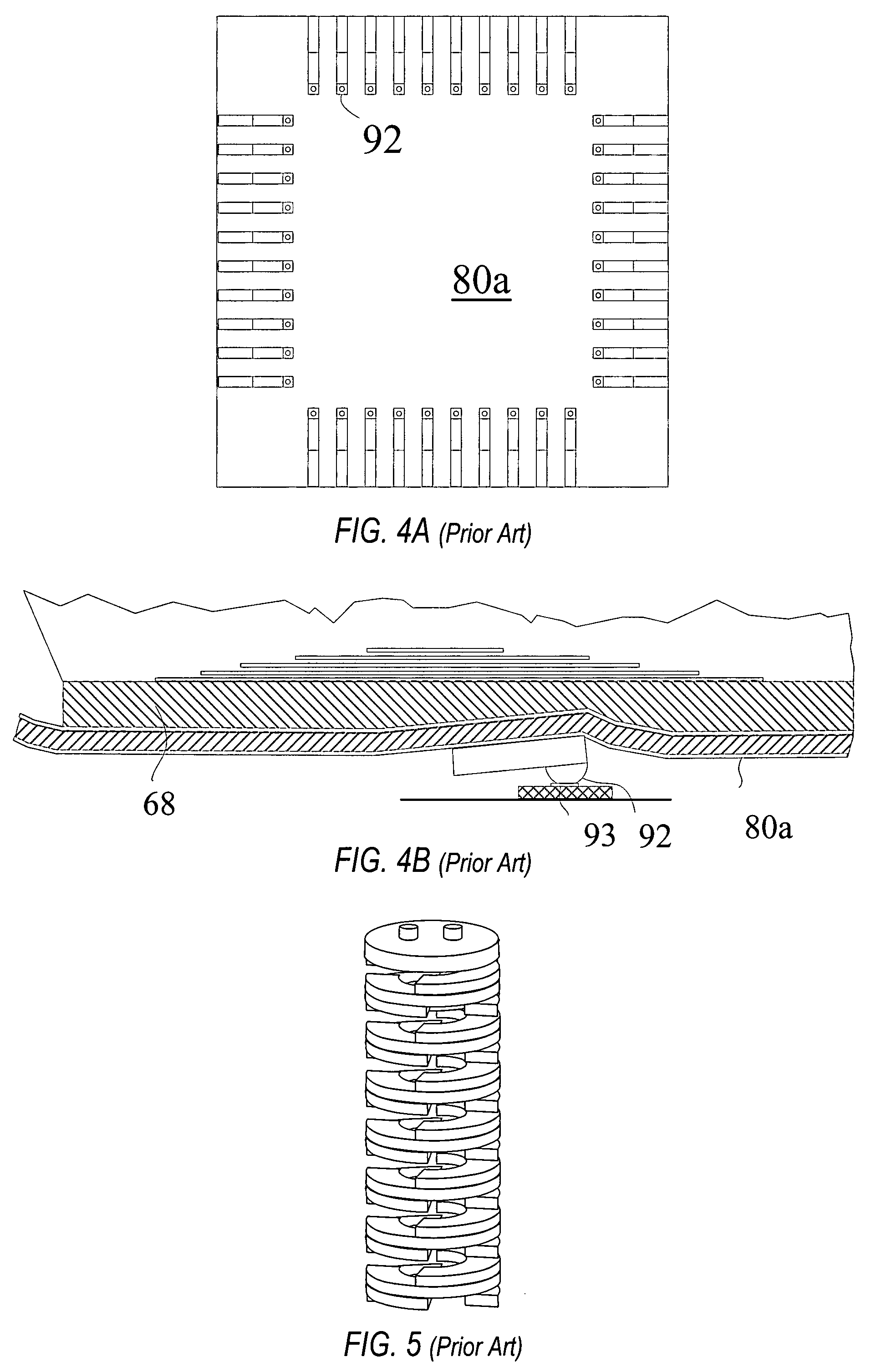
A disadvantage of this approach is that the interposer that makes electrical contact between the z-block and the thin HDI has vertical springs near the active area of the probe and not along the edges of the HDI where it is supported by the compliant membrane or mesh.
This force differential can cause the HDI to bow or tent and causes a planarity error at the tips of the probes.
Poor alignment can damage the insulating layer around the IC pads and insufficient mechanical scrub can affect the electrical reliability of the pad to probe contact.
Being a shorter spring, the electrical parameters are better but this type of spring makes contact to the IC pads with a shallow angle which results in a longer scrub mark.
As the area expands to full wafer memory testing, this architecture will result in a stack up of tolerances that cannot be managed without increasing the spring height.
Further, these springs 72 are a batch fabrication on the HDI and cannot be repaired if damaged.
However, this alignment cannot be maintained while the frame is being distorted by the mechanical and thermal forces experienced during the wafer testing process.
As the number of IC pads and temperature testing extremes increases, these architectures have difficulty scaling to match the needs.
Another problem encountered when attempting to test a full wafer at one time is that it is difficult to successfully build (yield) a large number of probes (up to 50,000) on the HDI over the area of a 300-mm wafer.
Many of the traditional approaches cannot probe larger areas because they need to fan out laterally to route out to the tester connectors.
Traditional approaches cannot scale to performing high performance testing while simultaneously providing electrical connections to all of the ICs on a full wafer.
Scaling of the HDI to match 300 mm and larger wafers is prohibitively expensive.

Method used


Image

  • Probe card repair using coupons with spring contacts and separate atachment points
  • Probe card repair using coupons with spring contacts and separate atachment points
  • Probe card repair using coupons with spring contacts and separate atachment points

Examples


Embodiment Construction

[0070]One objective in integrated circuit testing, particularly in memory testing, is to enable two touchdown or single touchdown full wafer testing applications, while eliminating the need to use an expensive and hard to manufacture 5-11 mm thick co-fired ceramic HDI that is large enough to cover the area of today's 300 mm or larger wafers. The traditional HDI / interposer approaches use a thick HDI to provide mechanical stability to eliminate bowing or flexing. The thick ceramic provides a relatively stiff support and planar surface to keep the springs contacting the DUT wafer to operate within its stress limits while maintain sufficient pressure to effect a reliable electrical contact to the DUT wafer. In contrast, the compliance partitioning architecture allows the HDI to flex and uses two sets of opposing springs to dynamically adjust to keep contact to the IC during testing.

[0071]One embodiment of the invention electrically and mechanically attaches low compliance (short) probes...


PUM

PropertyMeasurementUnit
frequencyaaaaaaaaaa
frequenciesaaaaaaaaaa
lengthsaaaaaaaaaa

Abstract

Probecard architectures partition the spring compliance required for IC testing between several different components. Such architectures can provide shorter springs, better impedance control, improved power / ground distribution and more direct paths to tester electronics. The probecards can also use thinner interconnector substrates to conform to the planarity of a DUT and may suspend such a substrate by wires attached to a perimeter edge of the substrate to permit the substrate to tilt. Tilting can also be facilitated by positioning tester-side springs away from the perimeter of the substrate. Low compliance MEMS probes for such architectures can be provided on replaceable coupons having attachment points away from electrical connections, and a method for fabricating probe springs can plate spring material on a membrane deformed by contact with a bumped substrate.

Description

CROSS-REFERENCE TO RELATED APPLICATIONS[0001]This patent document claims benefit of the earlier filing dates of U.S. Provisional Patent Application No. 60 / 844,139, filed Sep. 12, 2006 and U.S. Provisional Patent Application No. 60 / 921,812, filed Apr. 3, 2007, which are hereby incorporated by reference in their entirety.BACKGROUND[0002]Integrated circuits (ICs) are manufactured and tested in wafer form before being diced from the wafer and mounted in packages, modules, or directly on a printed circuit board. Wafer level IC testing is a critical part of the IC manufacturing process that identifies ICs that do not function properly and provides feedback for repair through programming of redundant logic as well as improving product design and reducing manufacturing cost. Wafer level IC testing also prevents non-functioning ICs from going through the cost of packaging and in some cases can be used for stress testing or burn-in testing at high temperature to screen ICs to improve long ter...

Claims


Application Information

Patent Timeline
Patent Type & Authority Patents(United States)
IPC IPC(8): G01R31/28
CPCC23C26/00G01R1/06727G01R1/07378G01R31/2891G01R1/07357Y10T29/4913
Inventor MOK, SAMMYSWIATOWIEC, FRANK J.AGAHDEL, FARIBORZ
Owner INNOCONNEX
Learn More