
Power amplifier circuit for multi-frequencies and multi-modes and method for operating the same

a power amplifier and multi-mode technology, applied in the direction of amplifiers, amplifiers with semiconductor devices/discharge tubes, dual/triple band amplifiers, etc., can solve the problems of power amplifiers facing even lower operation efficiency, power amplifiers becoming elements of low operation efficiency, and power amplifiers with high power consumption nature usually consume 13-12 electricity of the entire communication equipmen

Active Publication Date: 2011-01-25
IND TECH RES INST
View PDF3 Cites 70 Cited by
  • Summary
  • Abstract
  • Description
  • Claims
  • Application Information

AI Technical Summary

Benefits of technology

The solution enables efficient operation across various communication modes and frequencies, reducing power consumption and extending standby and communication times, while maintaining high efficiency and linearity, thus addressing the limitations of traditional power amplifiers.

Problems solved by technology

In the case of general system and environment, in most of the time the traditional power amplifier operates at an average output power region with low efficiency, and larger peak-to-average output power ratio means the power amplifier will face even lower operation efficiency.
This means the power amplifier becomes an element of low operation efficiency as digital modulating method becomes high level.
Unfortunately, the high power consumption nature of power amplifier usually consumes ⅓-½ electricity of the entire communication equipment.
Therefore for cell phones and the alike terminal equipments, low operation efficiency shortens standby and communication time.
For base stations and the alike central office equipments, besides the increase on the electricity bill of telecommunication business owns, the costs spending on cooling and large power equipments increase as well.
However, the Doherty amplifiers commonly available on the market mostly are of single-frequency and single-mode operation, the future of which is more and more facing challenge.
However, there is no the feature of adjustable average-to-peak output power point because of no external circuits that Doherty power amplifier needed.
Moreover, more groups of bias control circuits are required; and therefore the design complexity is increased and is only limited to single-frequency operation in frequency aspect.

Method used


Image

  • Power amplifier circuit for multi-frequencies and multi-modes and method for operating the same
  • Power amplifier circuit for multi-frequencies and multi-modes and method for operating the same
  • Power amplifier circuit for multi-frequencies and multi-modes and method for operating the same

Examples


Embodiment Construction

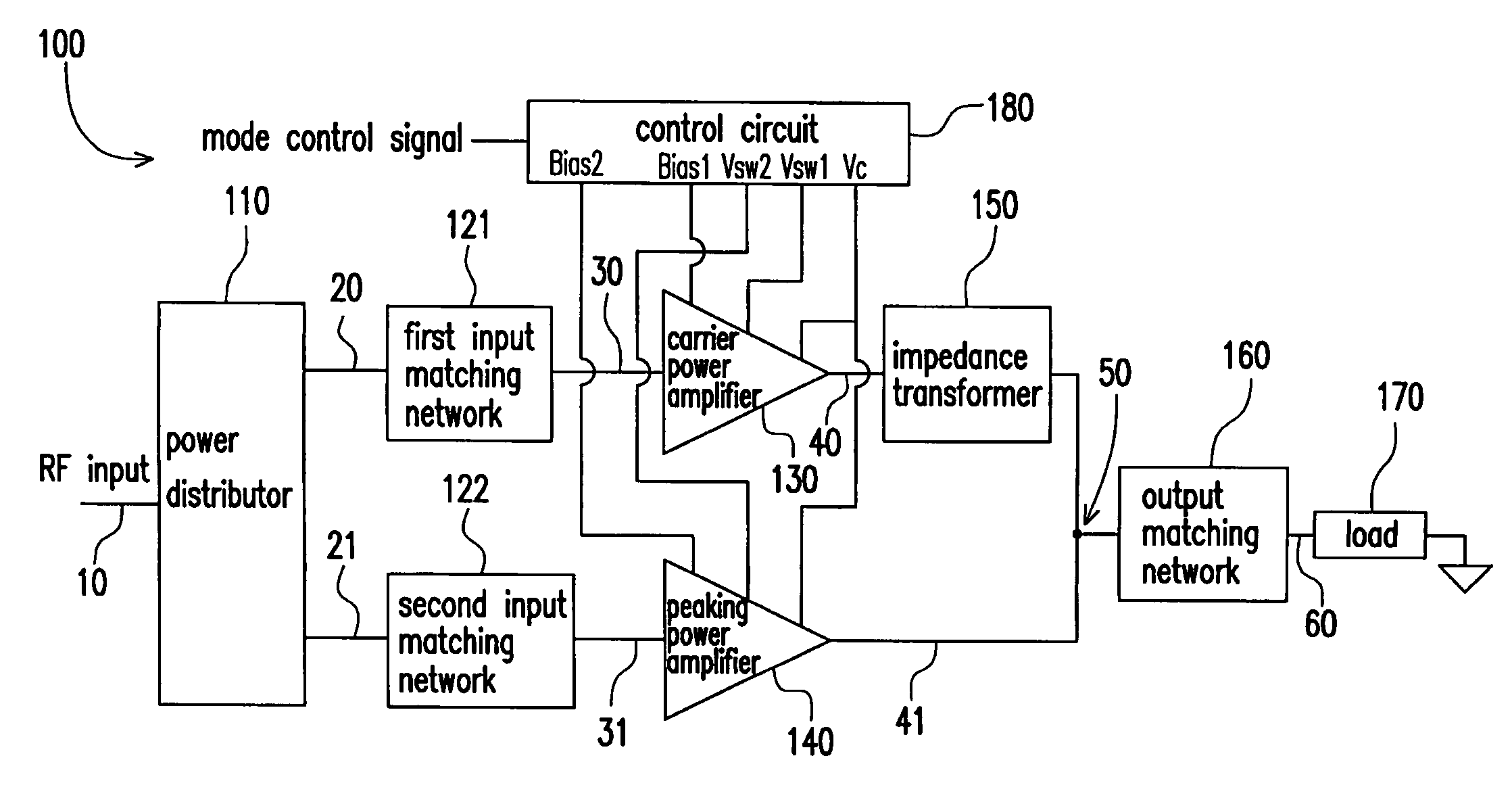
[0021]The multi-frequency and multi-mode power amplifying circuit of the present embodiment at least comprises an input signal processing unit, a carrier power amplifier, a peaking power amplifier and an output signal processing unit. For example, the above two power amplifiers form a Doherty power amplifier. The input signal processing unit is used to receive an RF signal and to output a first signal and a second signal. The input signal processing unit mainly performs power distribution for signals and input impedance matching with the following amplifiers. An input end of the carrier power amplifier is coupled to the input signal processing unit and receives the first signal to generate a first amplified signal. The carrier power amplifier further comprises a first transistor-size adjusting unit that adjusts an equivalent transistor size according to a mode indication signal. An input end of the peaking power amplifier is coupled to the input signal processing unit and receives t...


PUM


Abstract

A multi-frequency and multi-mode power amplifier is provided. The amplifier has a carrier power amplifier and a peaking power amplifier. The carrier power amplifier receives a first signal and outputs a first amplified signal, in which a first transistor size adjusting unit is included to adjust an equivalent transistor size based on a mode indication signal. The peaking power amplifier receives a second signal and outputs a second amplified signal, in which a second transistor size adjusting unit is included to adjust an equivalent transistor size based on the mode indication signal.

Description

CROSS-REFERENCE TO RELATED APPLICATION[0001]This application claims the priority benefit of Taiwan application serial no. 96130330, filed on Aug. 16, 2007. The entirety of the above-mentioned patent application is hereby incorporated by reference herein and made a part of this specification.BACKGROUND OF THE INVENTION[0002]The present invention relates to a power amplifier circuit and operation method thereof. More specifically, the present invention relates to a multi-frequency and multi-mode power amplifier circuit and operation method thereof.[0003]As people are anxious for the transmission volume of wireless communication system, high level digital modulating method starts to be widely used. The congenital modulating nature of the digital modulation requires that the power amplifier has higher peak-to-average output power ratio. In the case of general system and environment, in most of the time the traditional power amplifier operates at an average output power region with low e...

Claims


Application Information

Patent Timeline
Patent Type & Authority Patents(United States)
IPC IPC(8): H03F3/68
CPCH03F1/0288H03F1/56H03F2200/111
Inventor WANG, SHIH-MINGCHEN, CHENG-CHUNGHSU, YU-CHENGLAI, CHUNG-CHI
Owner IND TECH RES INST
Learn More