
Synchronizing apparatus and method in packet network

Active Publication Date: 2011-01-25
SAMSUNG ELECTRONICS CO LTD
View PDF16 Cites 47 Cited by
  • Summary
  • Abstract
  • Description
  • Claims
  • Application Information

AI Technical Summary

Benefits of technology

The verifying of the estimated propagation delay and the estimated time difference may comprise, where a new propagation delay sample value or a new time difference sample value is received, obtaining an error value by calculating a difference between the new propagation delay sample value and an average propagation delay or a difference between the new time difference sample value and an average time difference, where the error value is less than a first threshold value, determining that the new propagation delay sample value or the new time difference sam

Problems solved by technology

However, in an actual network, since network delay is asymmetrical, actual propagation delay in an uplink may be different from actual propagation delay in a downlink.
Since the delay times may be very stable and a time offset between the master device and the slave device appears as static time errors, the delay times may not increase delay variation values, such as jitter or wander.
However, in an actual network, where a slave device is connected to a master device via at least one bridge or routers that cannot process timestamp messages, time stamp messages that are transmitted by the master or slave device will be subjected to queuing delay which may randomly change over time, that is, according to traffic loads or traffic characteristics.
In this case, the queuing delay may vary by several ms, which may not satisfy the requirements regarding delay variation, such as jitter or wander, which may be required by general applications, such as timing control of a wireless base station, transmission of non-compressed digital video and audio, etc.
While messages including time stamps at an internode of a network may be transmitted first, since bridges and routers generally use a priority mechanism based on a non-preemptive scheduling scheme, the messages that contain the timestamps may be delayed due to packets that are currently being serviced.
As a result, in this case, delay variation may still occur in units of hundreds of μs.

Method used


Image

  • Synchronizing apparatus and method in packet network
  • Synchronizing apparatus and method in packet network
  • Synchronizing apparatus and method in packet network

Examples


Embodiment Construction

The following detailed description is provided to assist the reader in gaining a comprehensive understanding of the methods, apparatuses and / or systems described herein. Accordingly, various changes, modifications, and equivalents of the systems, apparatuses and / or methods described herein will be suggested to those of ordinary skill in the art. Also, descriptions of well-known functions and constructions are omitted to increase clarity and conciseness.

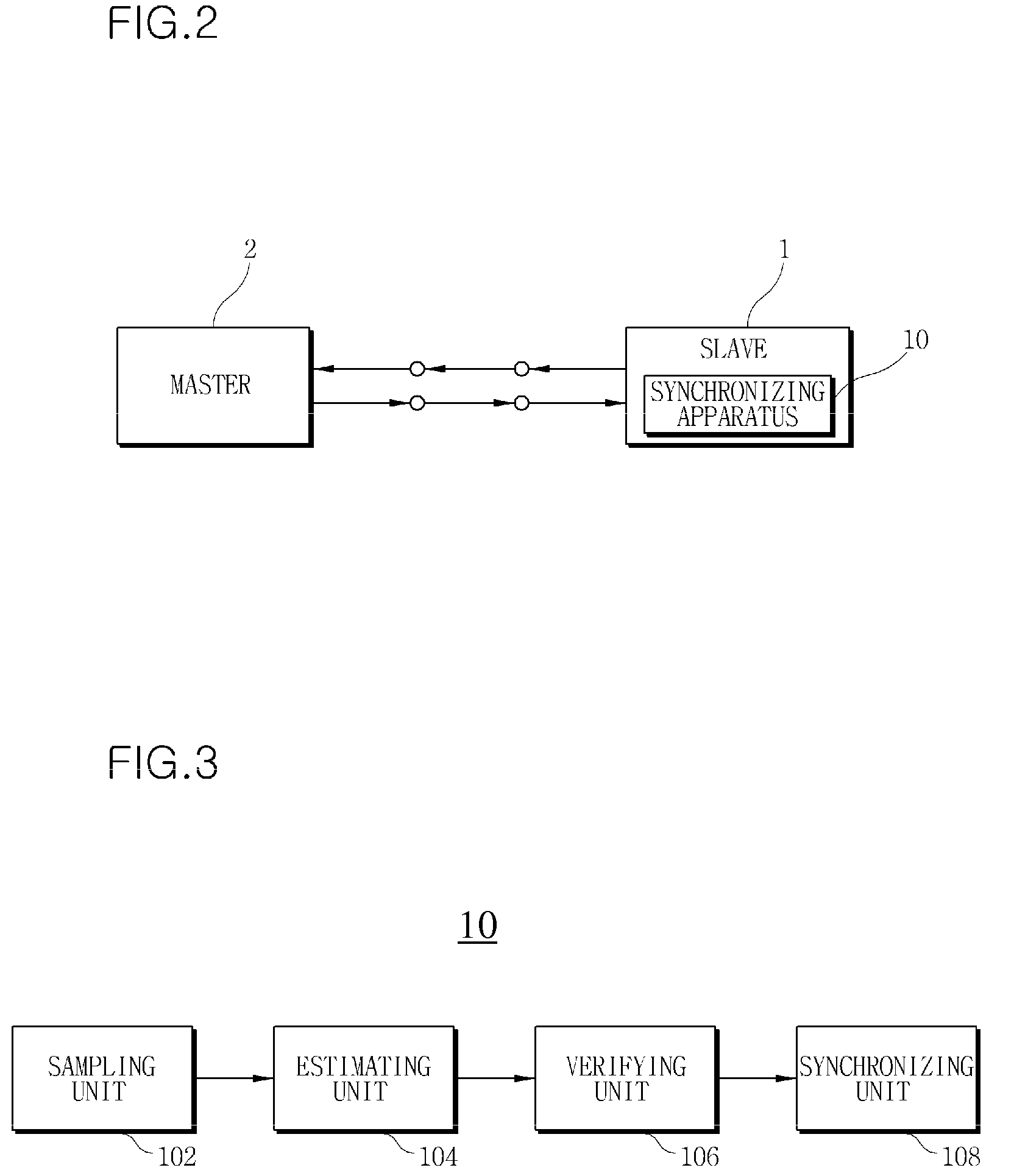
A baseline algorithm used in an exemplary embodiment will be described, followed by the configuration and operation of a synchronizing apparatus according to an exemplary embodiment.

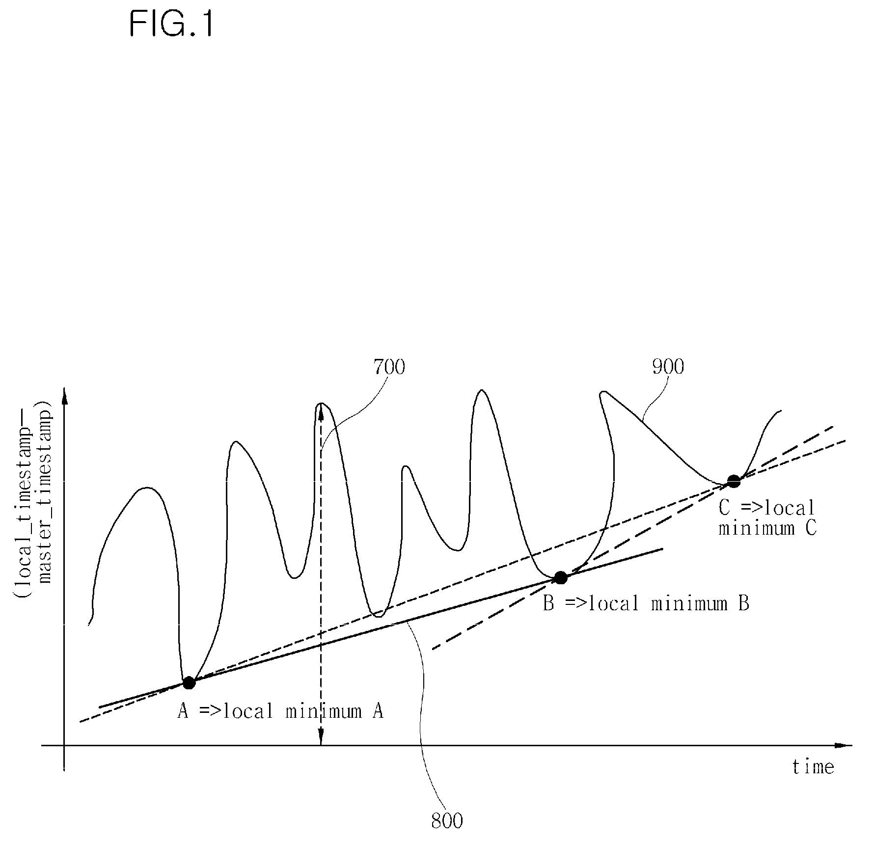
FIG. 1 shows a graph for explaining a baseline algorithm.

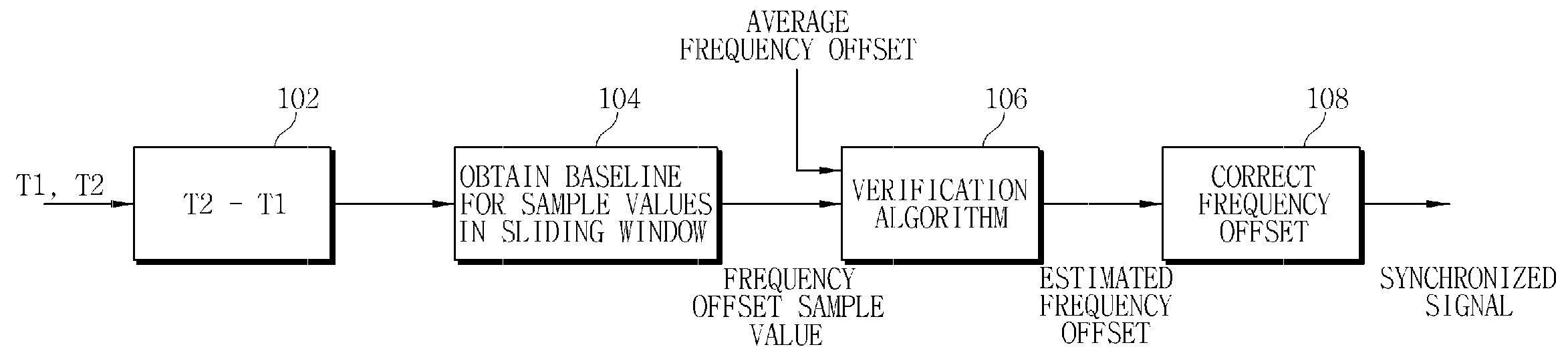
FIG. 1 is a graph plotting delay with respect to time where a baseline algorithm is used to estimate a frequency offset between two network nodes in the case where delay variation occurs due to network traffic. Transmitting and receiving nodes record time stamps in a message, and the receiving node m...


PUM


Abstract

Provided are a synchronizing apparatus and method for performing synchronization in a packet network. The synchronizing apparatus includes a sampling unit to measure a time difference using a plurality of time stamps included in a plurality of two-way message packets, an estimating unit to estimate a frequency offset by applying a baseline algorithm to the time difference, a verifying unit to verify the frequency offset to remove an error caused by network delay variation, and a synchronizing unit to remove the frequency offset from a local slave clock signal and generate a slave clock signal synchronized to a clock signal of a master device.

Description

TECHNICAL FIELDThe following description relates to network synchronization, and more particularly, to a synchronizing apparatus and method in a packet network.BACKGROUNDVarious protocols, such as the Network Time Protocol (NTP) standard, which transmit timings using time stamps, have been developed. In these protocols, each slave device generally uses a local free-running clock signal, and tries to synchronize the local free-running clock signal with a clock signal of a master device (for example, an IEEE 1588 grand master) when the slave device is connected to the master device.In general, when the slave device tries to synchronize with the master device, the slave device transmits to the master device a transmission message including a time stamp T1 regarding a transmission time. The master device receives the transmission message and transmits a response message to the slave device. This message transmission method may be referred to as a two-way message scheme. The response mes...

Claims


Application Information

Patent Timeline
IPC IPC(8): H04J3/06
CPCH04J3/0667H04J3/06H04L7/00
Inventor JUNG, HONG-KYUFENG, FEI FEIGARNER, GEOFFREY M.KIM, BYUNG-SUKLEE, CHUL-KI
Owner SAMSUNG ELECTRONICS CO LTD
Features
  • Generate Ideas
  • Intellectual Property
  • Life Sciences
  • Materials
  • Tech Scout
  • Unparalleled Data Quality
  • Higher Quality Content
  • 60% Fewer Hallucinations
Learn More