Device for detecting spatial position

a technology for detecting devices and positions, applied in the field of detecting devices for spatial positions, can solve problems such as life-threatening injuries and patient injury risks, and achieve the effects of convenient manipulation during operation, reliable immobilization of mounting devices, and simple manner

Inactive Publication Date: 2011-02-01
WEBER INSTR
View PDF23 Cites 18 Cited by
  • Summary
  • Abstract
  • Description
  • Claims
  • Application Information

AI Technical Summary

Benefits of technology

[0012]An object of the present invention is to propose a device for detecting spatial position, which is easier to manipulate during an operation. In particular, a reliable immobilization of the mounting device in an axial and a radial direction will be enabled in a simple manner.
[0015]The invention is based upon the knowledge that an immobilization of the mounting device in an axial and a radial direction can be reliably achieved in a simple manner using two angular ball bearings. These enable a zero-play immobilization in both an axial and a radial direction, thereby ensuring the precision of the detection of spatial position. In addition, ball bearings enable a particularly easy rotational bearing of the mounting device on the surgical instrument.
[0017]For axial immobilization, in one preferred embodiment a spring can be provided, which presses the mounting device against a stop located on the surgical instrument. With the force of this spring, zero-play immobilization in an axial direction is achieved.
[0019]To prevent the axial immobilization from becoming released, for example by the nut becoming loosened during handling of the surgical instrument, in one preferred embodiment the nut can be fixed in its desired position, for example, via laser welding, gluing or a mechanical mounting device.

Problems solved by technology

Thus if the surgical instrument alters its position relative to the device for detecting spatial position, this can result in a risk of injury to the patient.
An immobilization in the axial direction is of greatest importance, as otherwise the surgical instrument could, for example, be inserted too far through the opening in the mounting device into the patient, where it could cause life-threatening injuries.

Method used


Image

  • Device for detecting spatial position
  • Device for detecting spatial position

Examples


Embodiment Construction

[0030]Reference will now be made in detail to several embodiments of the invention that are illustrated in the accompanying drawings. Wherever possible, same or similar reference numerals are used in the drawings and the description to refer to the same or like parts or steps. The drawings are in simplified form and are not to precise scale. For purposes of convenience and clarity only, directional terms, such as top, bottom, up, down, over, above, and below may be used with respect to the drawings. These and similar directional terms should not be construed to limit the scope of the invention in any manner.

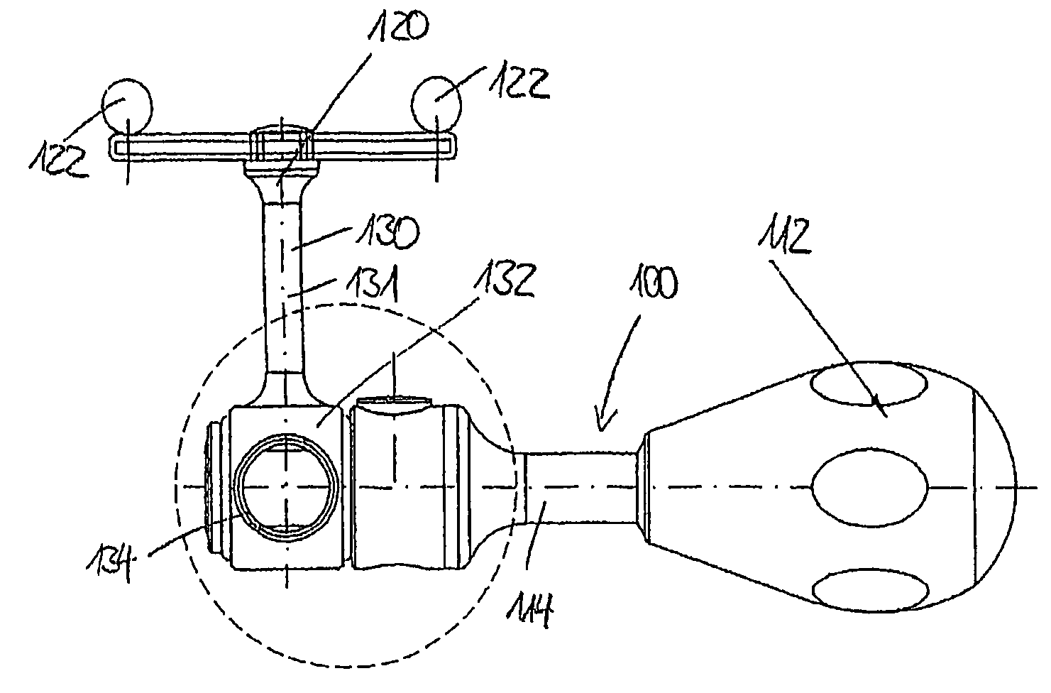
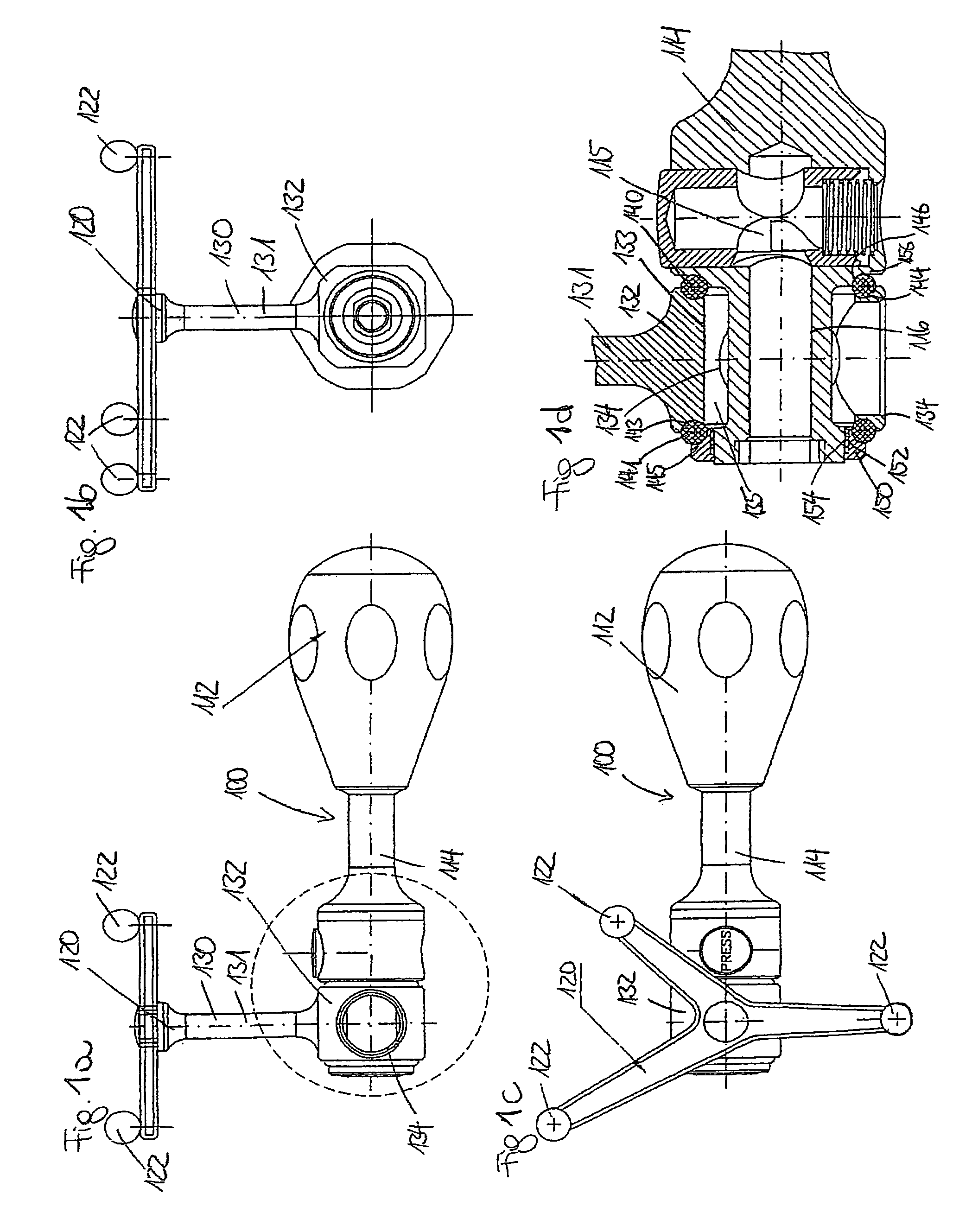
[0031]FIGS. 1a through 1d show a surgical instrument 100 with a handle 112, on which a shaft 114 is disposed. The longitudinal axis of the shaft 114 defines a longitudinal axis l100 of the surgical instrument.

[0032]The distal end of the shaft 114 is configured as a coupling 115, via which a working end can be placed on the shaft 114. To this end, a longitudinal bore hole 116 is l...


PUM


Abstract

The invention relates to a device for detecting spatial position, which can be attached via a mounting device to a surgical instrument, which has a longitudinal axis, wherein the mounting device has a through opening, which is penetrated by the instrument, wherein the mounting device is mounted so as to be rotatable around the longitudinal axis of the instrument, and wherein the mounting device can be immobilized in an axial and a radial direction via two angular ball bearings.

Description

CROSS REFERENCE TO RELATED APPLICATION[0001]This application relates to and claims priority from European Patent App. Ser. No. 07 007 972.8 filed Apr. 19, 2007, the entire contents of which are herein incorporated fully by reference.FIGURE SELECTED FOR PUBLICATION[0002]FIG. 1D.BACKGROUND OF THE INVENTION[0003]1. Field of the Invention[0004]The present invention relates to a device for detecting spatial position.[0005]2. Description of the Related Art[0006]Devices for detecting spatial position are known in the field of surgery, where they can be used to monitor surgical interventions. Such devices for detecting spatial position are disposed on the surgical instruments being used for the purpose of tracking them, and are therefore also referred to as trackers. Both active and passive trackers are known within this context.[0007]The passive trackers have reflectors, which reflect light emitted by optical transmitters located in the operating room, wherein the light reflected by the re...

Claims


Application Information

Patent Timeline
Patent Type & Authority Patents(United States)
IPC IPC(8): G01D21/00
CPCA61B19/52A61B19/54A61B19/5244A61B2017/00473A61B2019/4868A61B2019/5255A61B2019/5483A61B34/20A61B90/36A61B90/39A61B2034/2055A61B2090/0813A61B2090/3983
Inventor WEBER, HELMUT
Owner WEBER INSTR
Why Eureka
Try Eureka