Wind generator system

a wind generator and wind turbine technology, applied in the direction of electric generator control, renewable energy generation, greenhouse gas reduction, etc., can solve the problems of increasing the need for alternative sources of electrical energy, affecting the operation of wind generators, so as to increase the rotational speed of the drive shaft

Inactive Publication Date: 2011-02-01
STAR SAILOR ENERGY
View PDF41 Cites 22 Cited by
  • Summary
  • Abstract
  • Description
  • Claims
  • Application Information

AI Technical Summary

Benefits of technology

[0027]In another preferred embodiment of the invention the individual components of the wind generator system are grouped into individual modules that can be easily installed or removed into the wind generator system.
[0029]In another preferred embodiment of the invention the wind generator system comprises a wire or band formed from a shaped memory alloy and effective for increasing the rotational speed of the drive shaft.

Problems solved by technology

In recent years the need for alternative sources of electrical energy has grown significantly as a result of increased and uncertainty in oil prices, growing environmental concerns, and the lack of sufficient alternative energy supplies.
Unfortunately, while such systems have reduced maintenance costs and have increased the efficiency of the systems, wind generator systems continue to suffer from relatively significant maintenance costs.
Accordingly, high wind speeds often encountered by small wind generator systems, even if only occasional or momentary, can damage system components.
Unfortunately, all such means significantly add to the complexity and expense of the wind generator systems and significantly add to their maintenance down time and costs.
In addition, systems having such means typically require routine maintenance which significantly increases their operating costs.
This is particularly true when parts or components must be repaired or replaced which often requires significant rebuild or major dismantling of the system to replace a component.
Further, during operation, such means often result in significant power drops or the cessation of power generation during such high wind conditions.
Another problem associated with small wind generators is that they are often acoustically noisy and are undesirable for many residential applications.
Further, small or low wind generator systems for mounting to building structures are generally not aesthetically pleasing, often require extensive building modifications, and are prohibited under many building codes.
Accordingly, due to the complexity of many wind generators used in small wind or distributed power the need for a simple modular and easy to maintain generator is significant in not just reducing cost to the consumer but in the cost of manufacture and maintenance.

Method used


Image

  • Wind generator system
  • Wind generator system
  • Wind generator system

Examples


Embodiment Construction

[0060]The present invention relates to a low or small wind generator system. In describing the preferred embodiments of the invention illustrated in the drawings, specific terminology will be resorted to for the sake of clarity. However, the invention is not intended to be limited to the specific terms so selected, and it is to be understood that each specific term includes all technical equivalents that operate in a similar manner to accomplish a similar purpose.

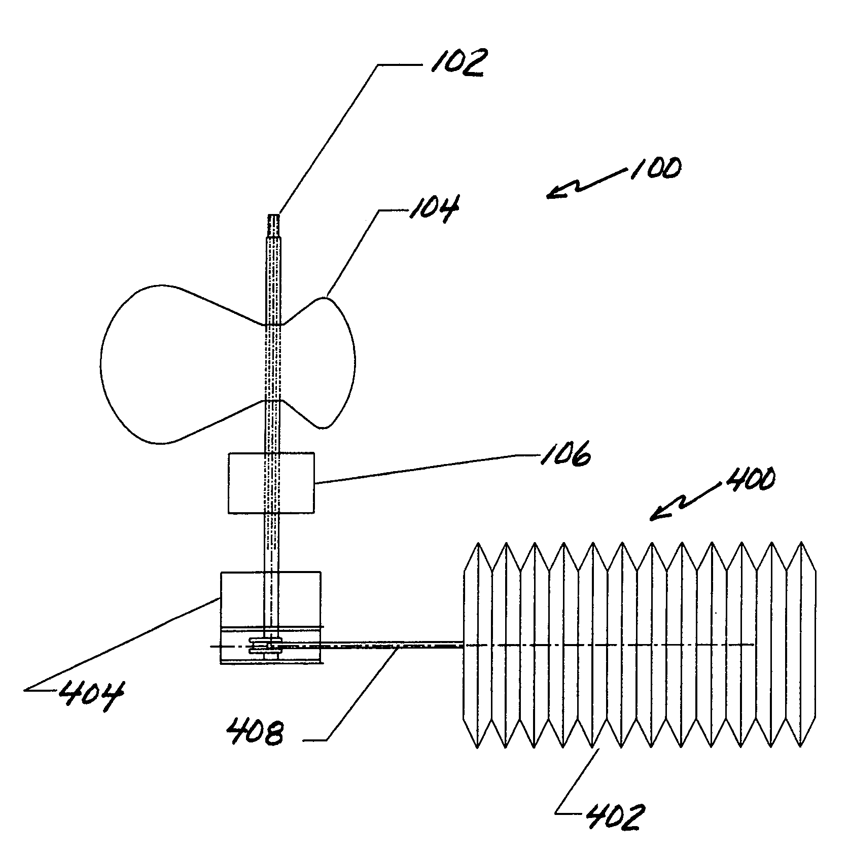
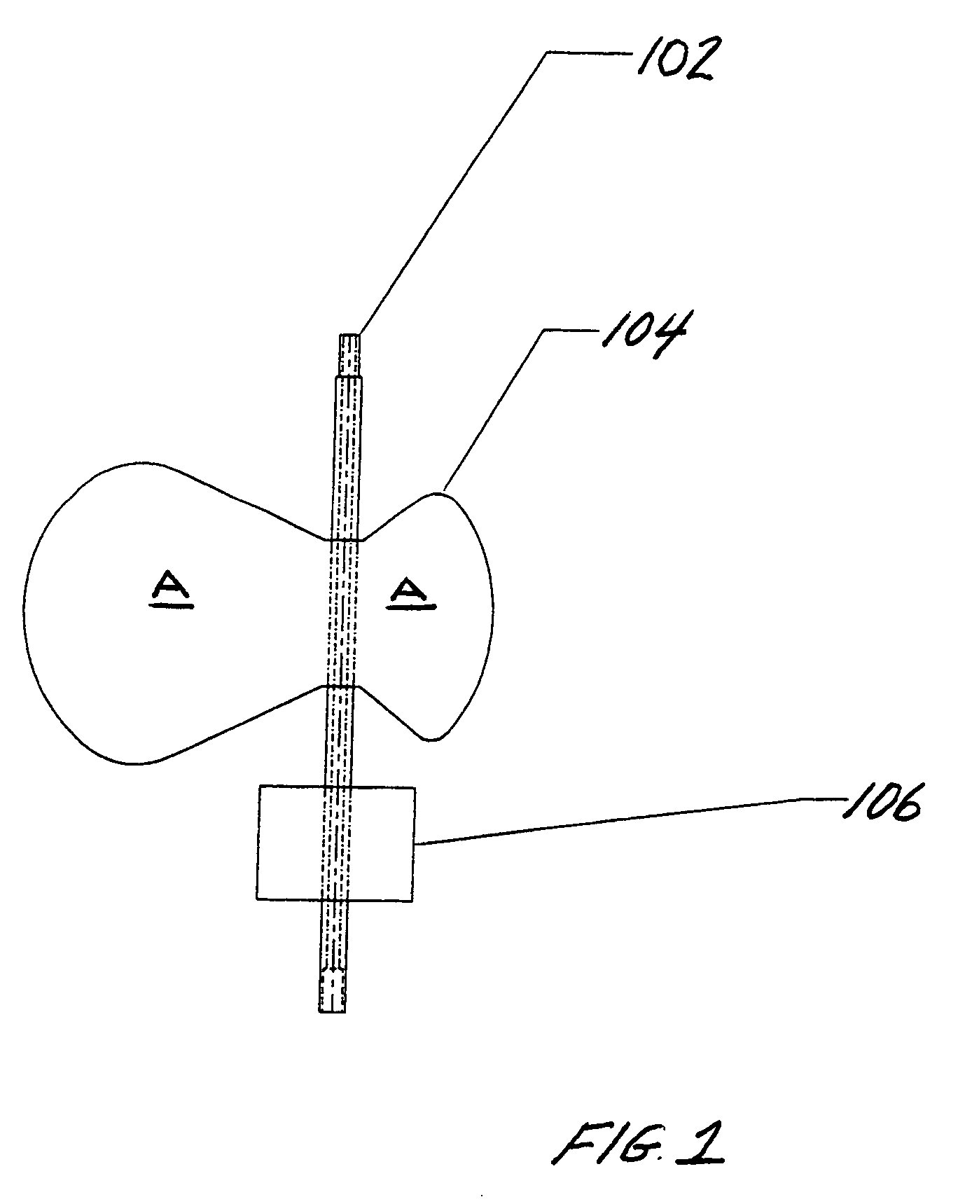
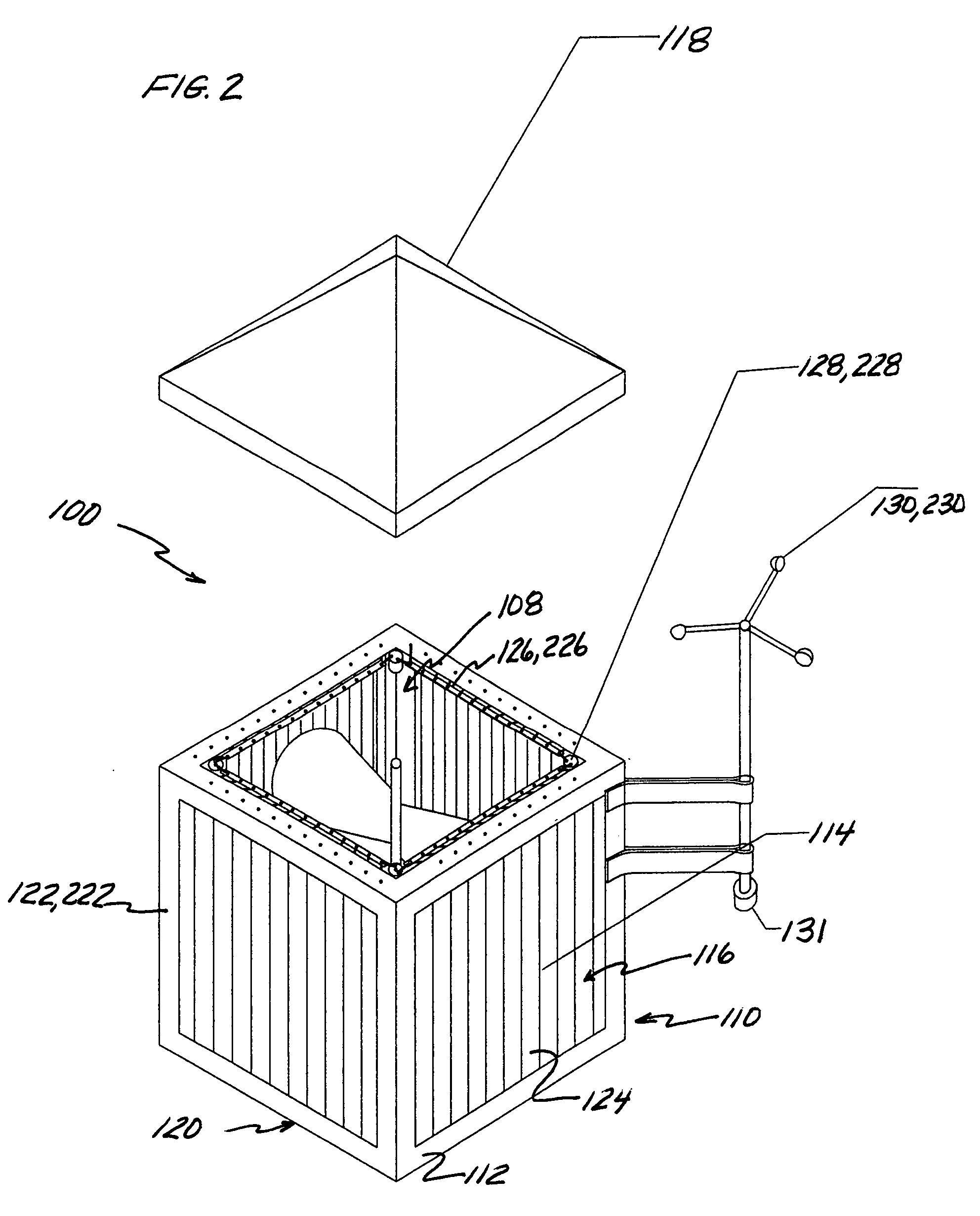
[0061]Referring to FIGS. 1 and 2, a preferred embodiment of the wind generator system, generally referred to as 100, is shown comprising a drive shaft 102 and a plurality of blades 104 (two or more) attached to and extending radially outwardly from the drive shaft 102. The drive shaft 102 is operationally coupled to a generator assembly 106 which operates to generate electrical power when actuated by rotation of the drive shaft 102. It should be understood that as used herein the term “generator” includes alternators. In a ...


PUM


Abstract

A new and novel wind generator system particularly suitable for small wind applications that harnesses low velocity wind effectively. In a preferred embodiment, the wind generator system has a drive shaft; a plurality of blades attached to the drive shaft and extending radially outwardly therefrom; a generator assembly coupled to the drive shaft and effective for generating electrical power; and a housing having an inner chamber for receiving the plurality of blades and a wind directional apparatus that operates to adjust the speed of the wind and to channel wind along a desired flow pathway towards the plurality of blades.

Description

TECHNICAL FIELD[0001]The present invention is directed to power generation and, more particularly, to wind generator systems effective for generating electric power during low wind conditions and in urban or built environments.BACKGROUND OF THE INVENTION[0002]In recent years the need for alternative sources of electrical energy has grown significantly as a result of increased and uncertainty in oil prices, growing environmental concerns, and the lack of sufficient alternative energy supplies. Accordingly, wind generator systems have gained support as an alternate energy source. Wind generators have been shown to provide a safe and clean source of electric power. Systems, such as large or big wind generators, have been developed having large blades (often more that 18 feet in length) mounted on high towers that can produce more than 35 kilowatts (kW) of power with wind speeds of 20 knots. Such systems are typically used in combination with other wind generators, such as along coastal...

Claims


Application Information

Patent Timeline
Patent Type & Authority Patents(United States)
IPC IPC(8): F03G3/00F03D7/00
CPCF03D3/005F03D3/0409F03D9/002F05B2240/216F05B2240/911Y02B10/30Y02E10/728Y02E10/74F03D9/25Y02E60/16F03D15/20F03D9/34F03D9/12F03D9/17F03D3/02F03D3/0454Y02E70/30F03D3/0418F03D3/062F03D7/06
Inventor MENGES, PAMELA A.
Owner STAR SAILOR ENERGY
Why Eureka
Try Eureka