

Sintered magnet and rotating machine equipped with the same
a technology of sintered magnets and rotating machines, applied in the direction of magnetic circuit rotating parts, magnetic circuit shapes/forms/construction, magnetic bodies, etc., can solve the problems of ineffective use of fluoride compounds or the like, difficulty in using conventional techniques to magnets with thicknesses exceeding 10 mm, etc., to achieve high resistivity, high coercivity, and high magnetic flux density
- Summary
- Abstract
- Description
- Claims
- Application Information
AI Technical Summary
Benefits of technology
Problems solved by technology
Method used
Image

Examples
first embodiment
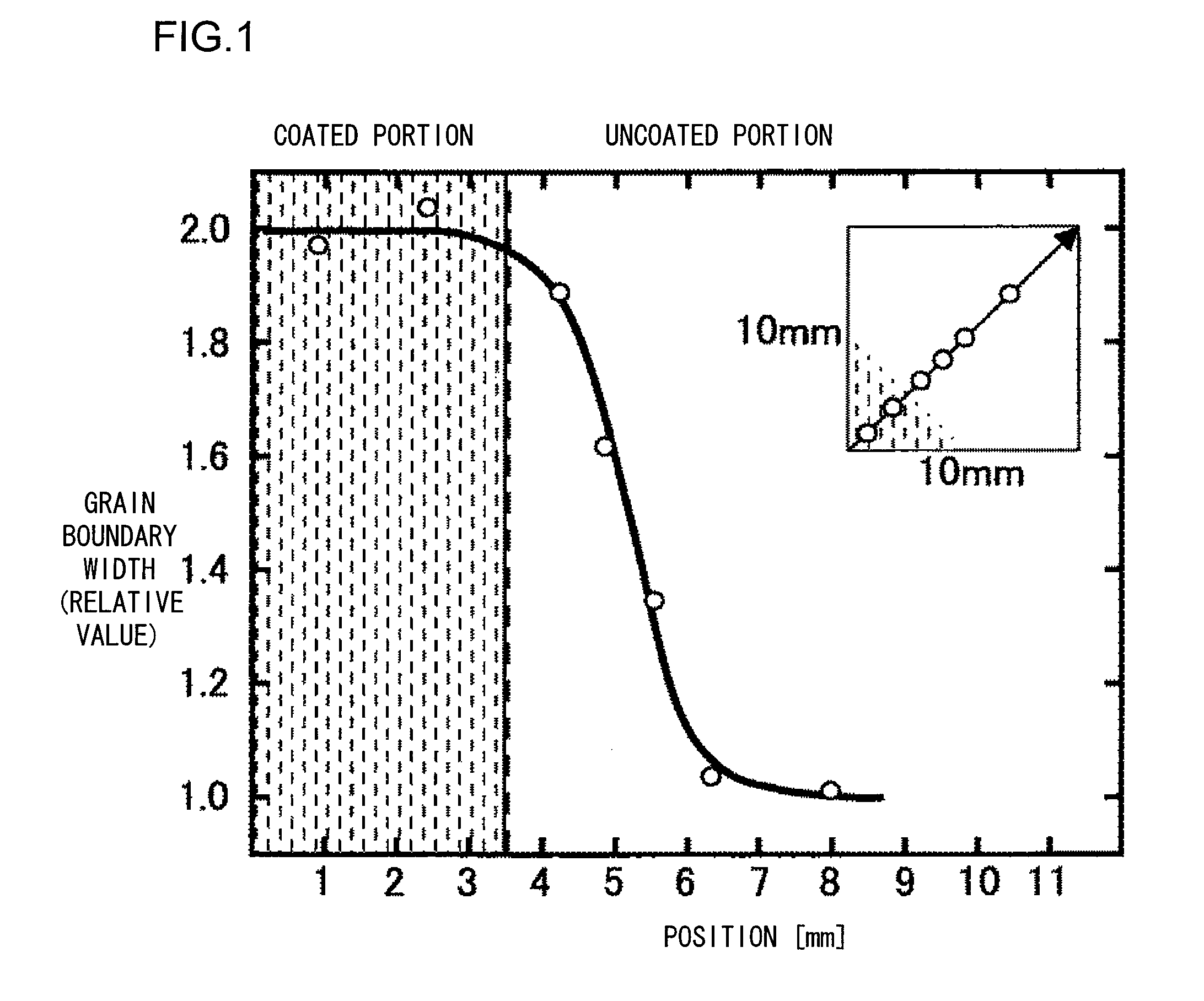
Magnetic powder with an average particle diameter of 5 μm consisting mainly of Nd2Fe14B and containing about 1% boride and a rare earth-rich phase is prepared as an NdFeB series magnetic powder. The magnetic particles are charged in a mold and pressed at a load of 1 t / cm2 in a magnetic field of 1 T to prepare a preformed body. The preformed body is sintered at a temperature between 1,000° C. and 1,150° C. under a vacuum of 1×10⁻³ Pa or lower. Surface polishing makes the size of the magnet to 10×10×5 mm3. The orientation direction is a direction of the 5 mm side. The sintered magnet has a coercive force of 10 kOe at 25° C. It is preferred that only the face parallel to or sides perpendicular to the orientation direction of the sintered body, or portions of the sintered body to which an alternating magnetic field is intensely applied or portions where the alternating magnetic field is relatively intense when it is mounted in a motor are soaked in a DyFx solution. The DyFx solution is ...
second embodiment
Magnetic powder with an average particle diameter of 5 μm consisting mainly of Nd2Fe14B and containing about 1% boride and a rare earth-rich phase is prepared as an NdFeB series magnetic powder. In order to form DyF3 on the surface of the magnetic particles, Dy (CH3COO)3 as a starting material is dissolved with H2O and HF is added thereto. By addition of HF, gelatinous DyF3.XH2O or DyF3.X(CH3COO) (where X is a positive integer) is formed. The resultant is centrifuged to remove the solvent and alcohol is added to the residue to obtain a solution that is optically transmissive. The obtained solution is coated on the magnetic particles, and the solvent is evaporated by vacuum degasification to attach DyFx to the magnetic particles. The thus obtained magnetic particles are charged in a mold and pressed at a load of 2 t / cm2 and in a magnetic field of 1 T to prepare a preformed body. The preformed body is sintered at a temperature between 1,000° C. and 1,150° C. under a vacuum of 1×10⁻³ P...
third embodiment
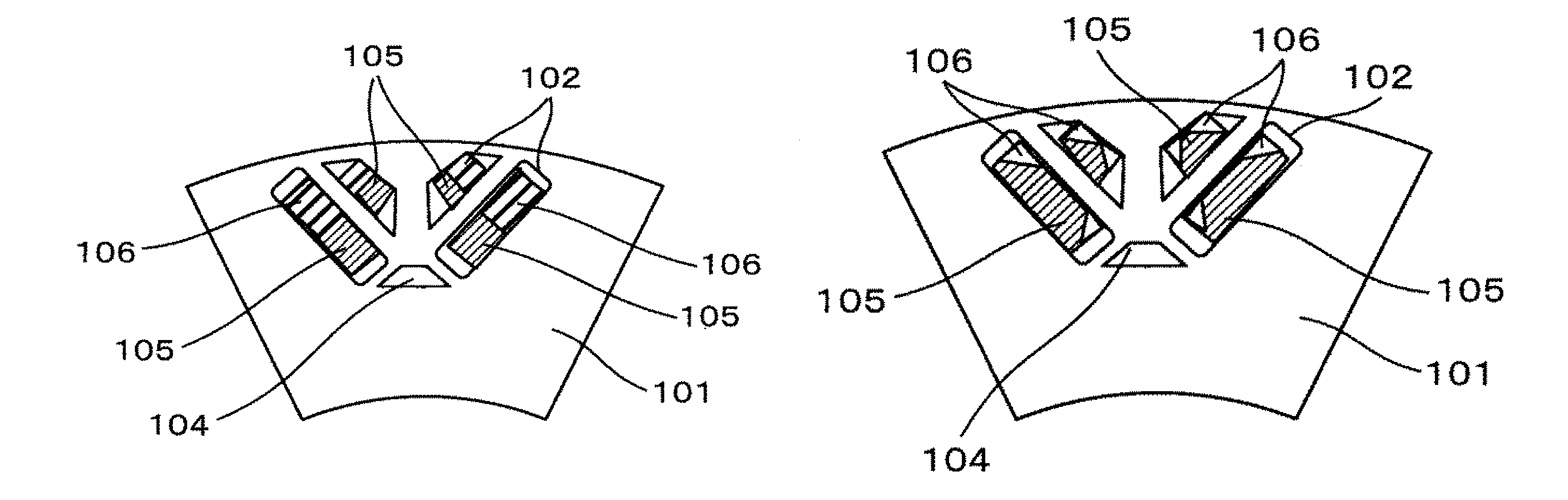
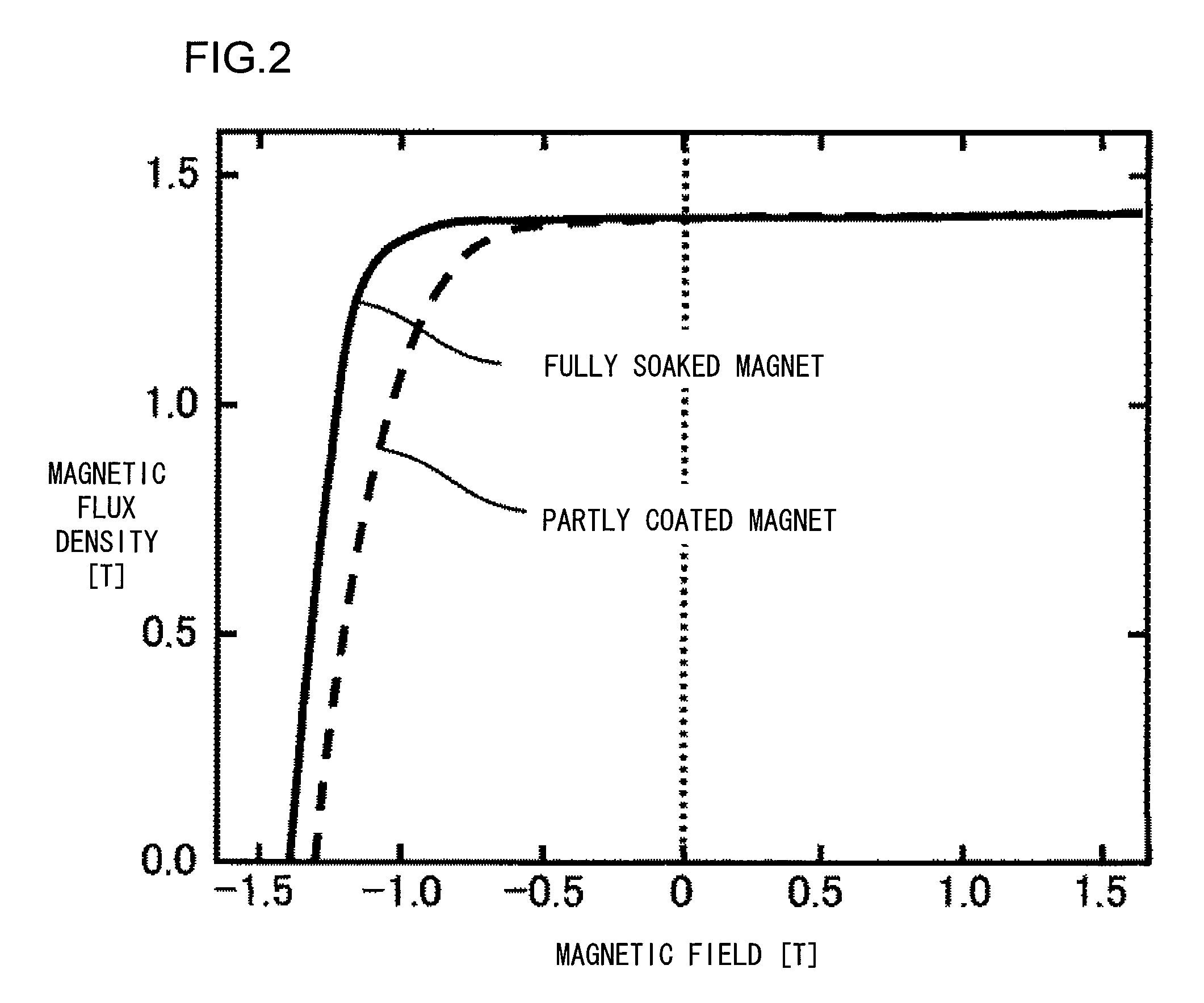
Magnetic powder with an average particle diameter of 5 μm consisting mainly of Nd2Fe14B and containing about 1% boride and a rare earth-rich phase is prepared as an NdFeB series magnetic powder. The magnetic particles are charged in a mold and pressed at a load of 1 t / cm2 in a magnetic field of 1 T to prepare a preformed body. The size of the preformed body is set to 10×10×15 mm3. The orientation direction is a direction of the 15 mm side. The preformed body has continuous gaps. It is preferred that only the face parallel to or sides perpendicular to the orientation direction of the sintered body, or portions of the sintered body to which an alternating magnetic field is intensely applied when it is mounted in a motor are soaked in a solution that is optically transmissive. On this occasion, only the four sides of the preformed body which are 15 mm long are soaked in a length of about 2 mm as measured in the diagonal direction.
For comparison, a fully soaked magnet is also fabricated...
PUM
| Property | Measurement | Unit |
|---|---|---|
| thicknesses | aaaaa | aaaaa |
| thickness | aaaaa | aaaaa |
| temperature | aaaaa | aaaaa |
Abstract
Description
Claims
Application Information