
Low-powered autonomous radio node with temperature sensor and crystal oscillator

a radio node, crystal oscillator technology, applied in the direction of generator stabilization, wireless commuication services, transmission systems, etc., can solve the problems of network bandwidth utilization, capacity limitations, and inefficiency of bandwidth utilization of battery powered wireless systems, so as to maximize power life, minimize the duty cycle of intelligent nodes, and efficient use of spectrum

Active Publication Date: 2011-02-01
ANALOG DEVICES INT UNLTD
View PDF63 Cites 15 Cited by
  • Summary
  • Abstract
  • Description
  • Claims
  • Application Information

AI Technical Summary

Benefits of technology

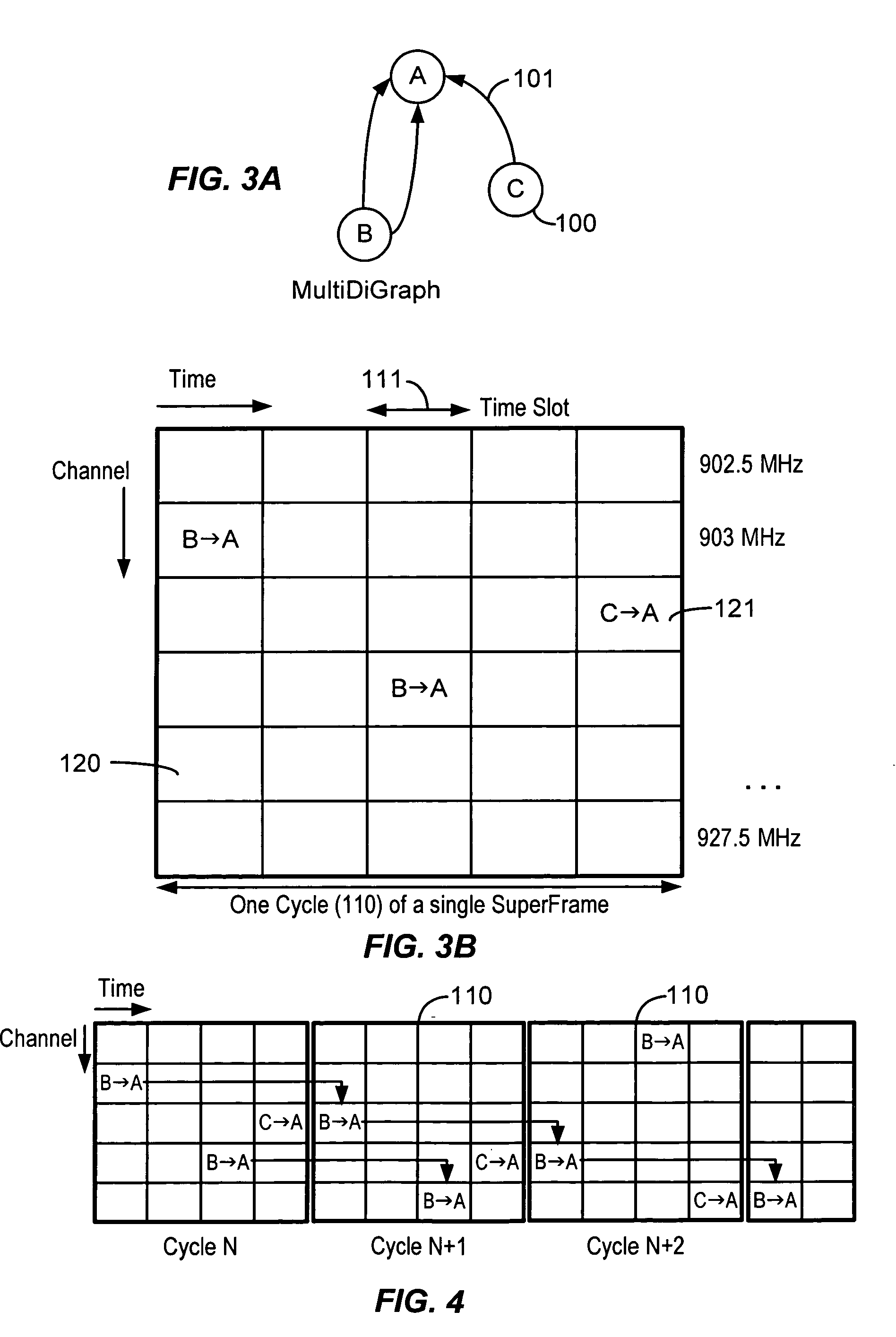
[0026]According to the invention, in a packet communication network, a method and apparatus for packet switched transport is provided among intelligent nodes wherein the duty cycling of the intelligent nodes is minimized in order to maximize power life using a synchronization algorithm that assures all nodes are able to propagate information through the network without undue use of transmission and reception power. Frequency hopping time-division multiple access supports packet communication between intelligent nodes via assigned directed links, each link being assigned to a time-channel offset (cell) in a superframe, so that a link carrying a packet string between any two intelligent nodes is active only during its assigned time slot. The result is efficient use of spectrum and minimal expenditure of power. If multiple superframes are employed and all frequency slots are simultaneously operating in synchronicity, the spectrum has the potential for 100% data utilization, less guard band spectrum.

Problems solved by technology

As the size, power, and cost of the computation and communication requirements of these devices has decreased over time, battery powered wireless systems have become smaller and smaller.
Packet switched networks, as opposed to circuit switched networks, are susceptible to multiple simultaneous communication and connectivity with competing data sources, so that packet collisions can result.
Absent control over access, such networks suffer from inefficiency of bandwidth utilization and capacity limitations due to collisions among packets transmitted at the same time and sharing the same spectrum.
Consequently, packets may be lost and thus must be retransmitted to complete message, resulting in substantial loss of efficiency.

Method used


Image

  • Low-powered autonomous radio node with temperature sensor and crystal oscillator
  • Low-powered autonomous radio node with temperature sensor and crystal oscillator
  • Low-powered autonomous radio node with temperature sensor and crystal oscillator

Examples


Embodiment Construction

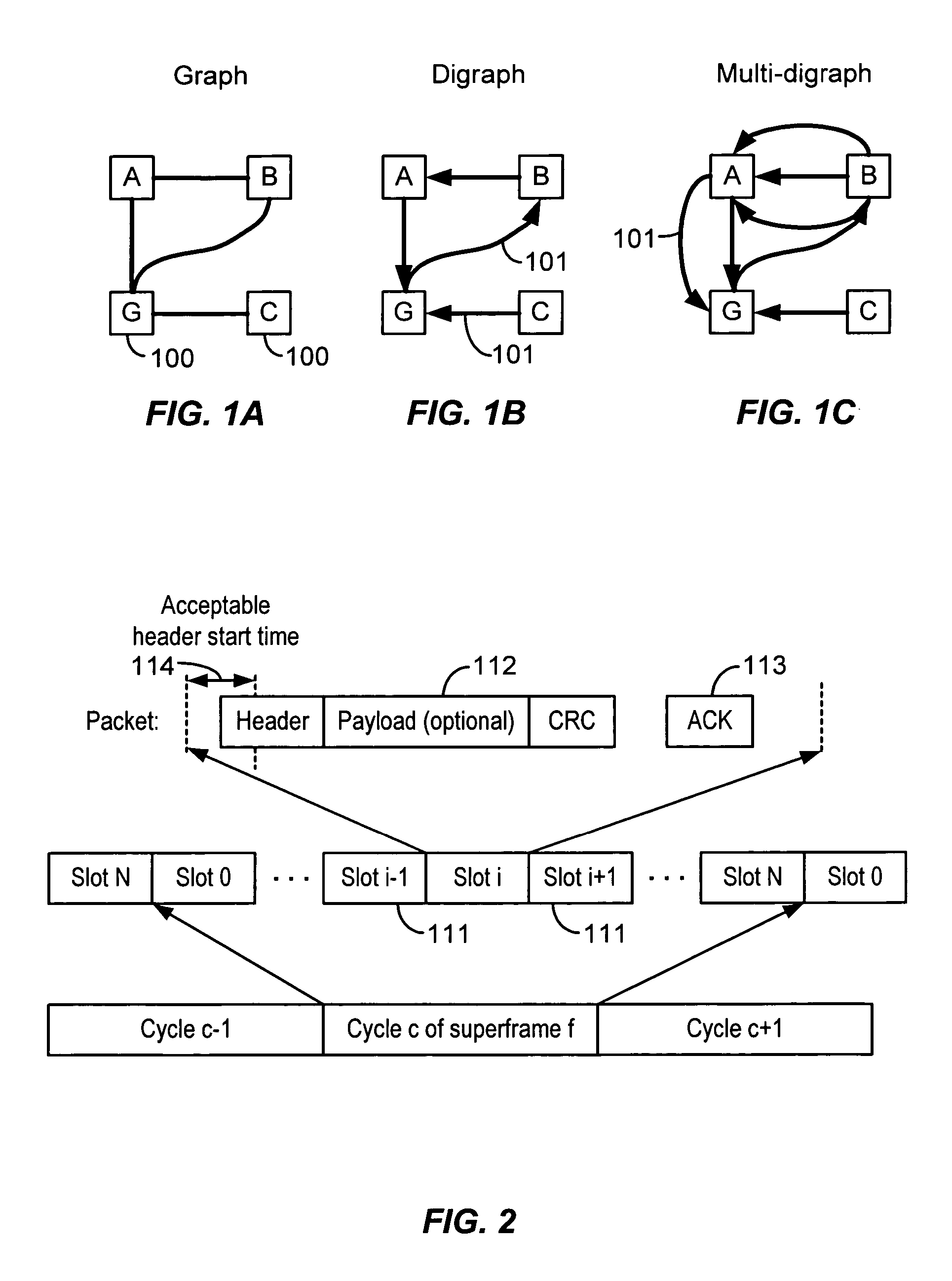
[0042]In a sensor network, which is one application of the invention, the vertices of a graph, representing the topology of the network, are the sites of intelligent nodes, also designated “motes,” either physical or symbolic, which are capable of analyzing incoming traffic and sensory data and which can act upon the traffic, reroute traffic and originate information from the site. Directed links (101FIG. 1B) between intelligent nodes A, B, C, G represent communication slots, and multiple links or slots (FIG. 1C) provide a mechanism for exhibiting relative available bandwidth between intelligent nodes. Every directed link in a digraph has the capability of transporting one packet in a given communication slot (FIG. 2). Each of these slots has a fixed length and admits the construction of a superframe (FIG. 2) which defines how the links in a given digraph will be distributed in time and frequency.

[0043]Referring to FIG. 2, in accordance with the invention, a slot is a period of time...


PUM


Abstract

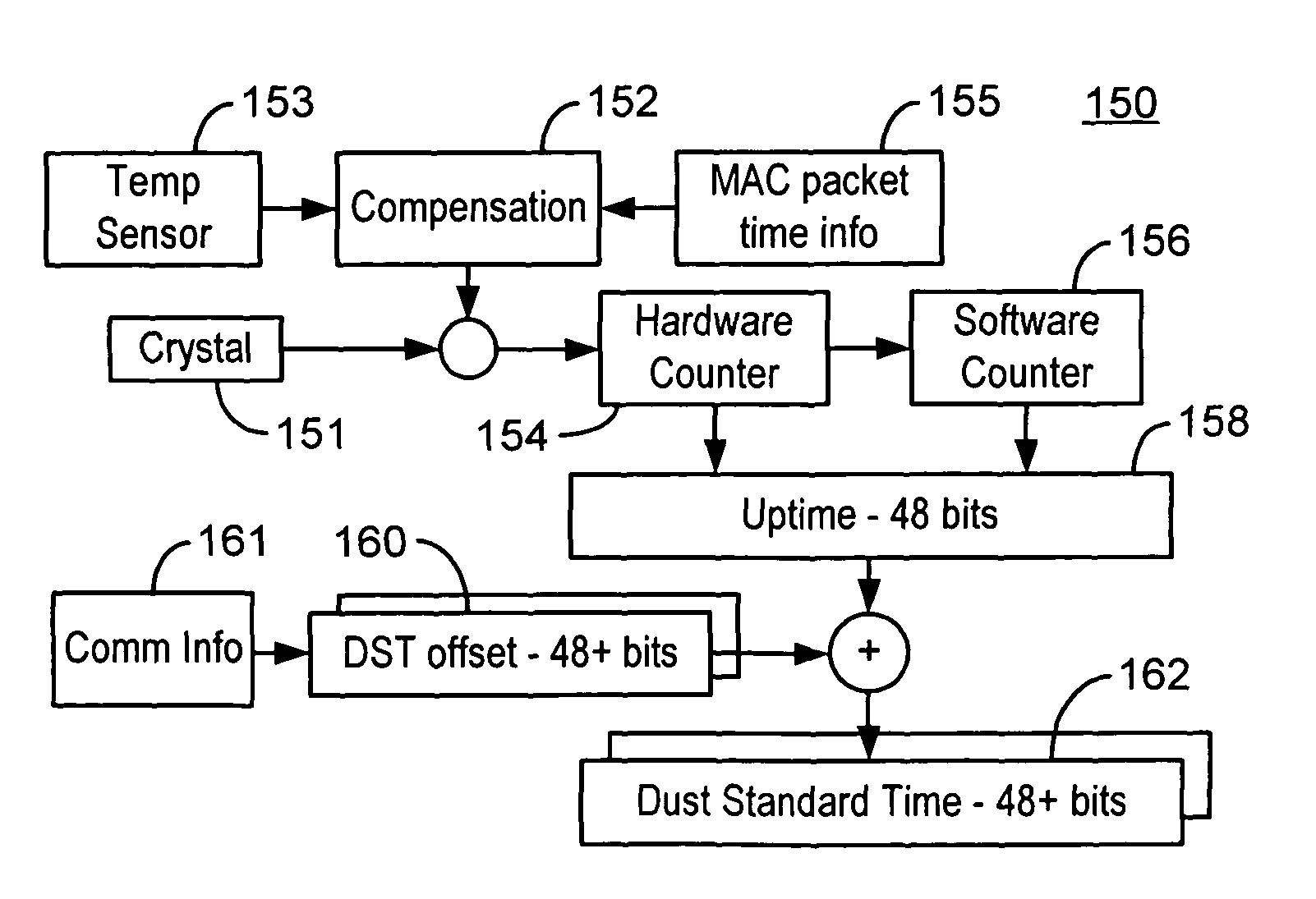
A device for a node in a digraph network comprising is disclosed. The device comprises an internal time reference, a radio receiver, a radio transmitter. The device further comprises a temperature sensor for stabilizing the internal time reference against drifting with respect to an internal time reference of another node in the network and a microprocessor for managing the reception and transmission of information.

Description

CROSS REFERENCE TO OTHER APPLICATIONS[0001]This application claims priority to U.S. Provisional Patent Application No. 60 / 557,148 entitled COMMUNICATIONS PROTOCOL FOR REMOTE SENSOR NETWORKS filed Mar. 27, 2004 which is incorporated herein by reference for all purposes.[0002]This application is a continuation of co-pending U.S. patent application Ser. No. 10 / 960,709 entitled LOW-POWERED AUTONOMOUS NODE FOR MESH COMMUNICATION NETWORK filed Oct. 6, 2004 which is incorporated herein by reference for all purposes.[0003]Co-pending U.S. patent application Ser. No. 10 / 914,056 entitled DIGRAPH BASED MESH COMMUNICATION NETWORK filed Aug. 5, 2004 is incorporated herein by reference for all purposes.BACKGROUND OF THE INVENTION[0004]This invention relates to wireless data networks and more particularly to a multiple-hop wireless radio frequency mesh network routing scheme employing a packet switched frequency-hopping spread spectrum time-sharing communications protocol. This invention has partic...

Claims


Application Information

Patent Timeline
Patent Type & Authority Patents(United States)
IPC IPC(8): G08C17/00H04W4/00H04J3/06H04L12/28H04L12/56
CPCH03L1/02H04J4/00H04W40/02H04W56/00H04W88/02Y02D30/70
Inventor PISTER, KRISTOFER S. J.ZATS, YURI S.CONTANT, ROBERT ALANTREUHAFT, NOAH
Owner ANALOG DEVICES INT UNLTD
Learn More