
Microinjection apparatus and microinjection method

a micro-injection apparatus and micro-injection technology, applied in the field of micro-injection apparatus and micro-injection method, can solve the problems of poor introduction efficiency, limited chemical methods, and large damage to the cell

Active Publication Date: 2011-02-01
FUJITSU LTD
View PDF9 Cites 8 Cited by
  • Summary
  • Abstract
  • Description
  • Claims
  • Application Information

AI Technical Summary

Benefits of technology

The present invention is about a microinjection apparatus and method that can inject objects into adherent cells with a needle. The apparatus includes an image acquiring unit that can capture a magnified image of the needle's leading edge, a needle detecting unit that can identify the leading edge of the needle, a shape judging unit that can determine the shape of the leading edge of the needle, and a needle shifting unit that can move the needle in a certain direction based on the shape of the leading edge. The technical effect of this invention is to improve the accuracy and efficiency of microinjection into adherent cells.

Problems solved by technology

Among those methods, the electrical method includes breaking a cell membrane by running a large current, giving a big damage to the cell.
The chemical method is limited in the number of genes to be introduced and is poor in respect of introduction efficiency.
The biological method has the defects such as that it there is a limitation on the number of materials to be introduced and that safety of this method cannot be confirmed.
Therefore, each time a needle is changed, adjustment of the position of the needle must be conducted manually by an experienced worker, forcing an increase in working hour and workload.

Method used


Image

  • Microinjection apparatus and microinjection method
  • Microinjection apparatus and microinjection method
  • Microinjection apparatus and microinjection method

Examples


Embodiment Construction

[0039]Exemplary embodiments of the present invention will now be described in detail by referring to the accompanying drawings.

[0040]The embodiments relate to automatically illuminating a cell that is located at a bottom surface of a petri dish, and while watching the cell with a CCD camera, adjusting a vertical position of a capillary and injecting an object present in the capillary into the adherent cell.

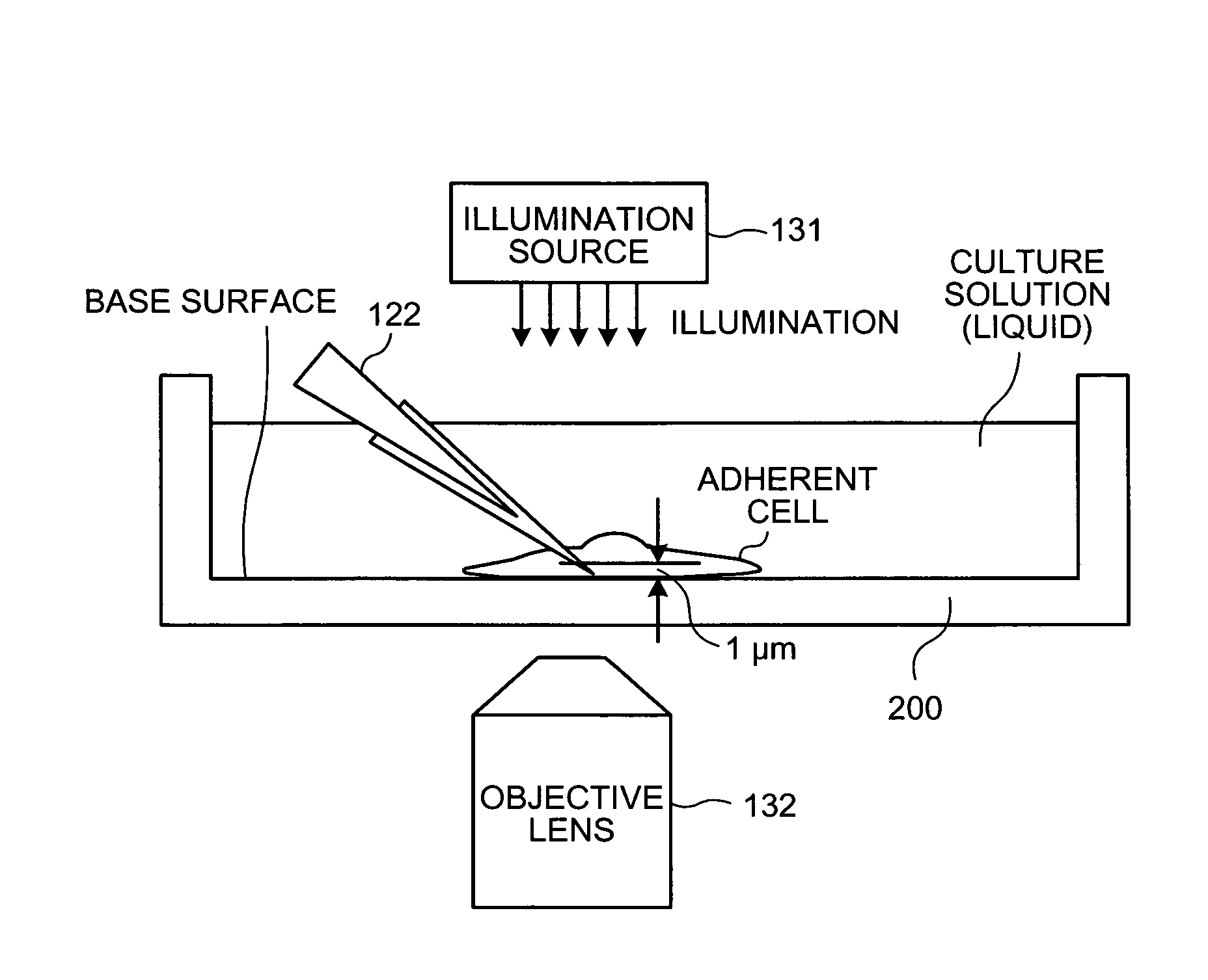
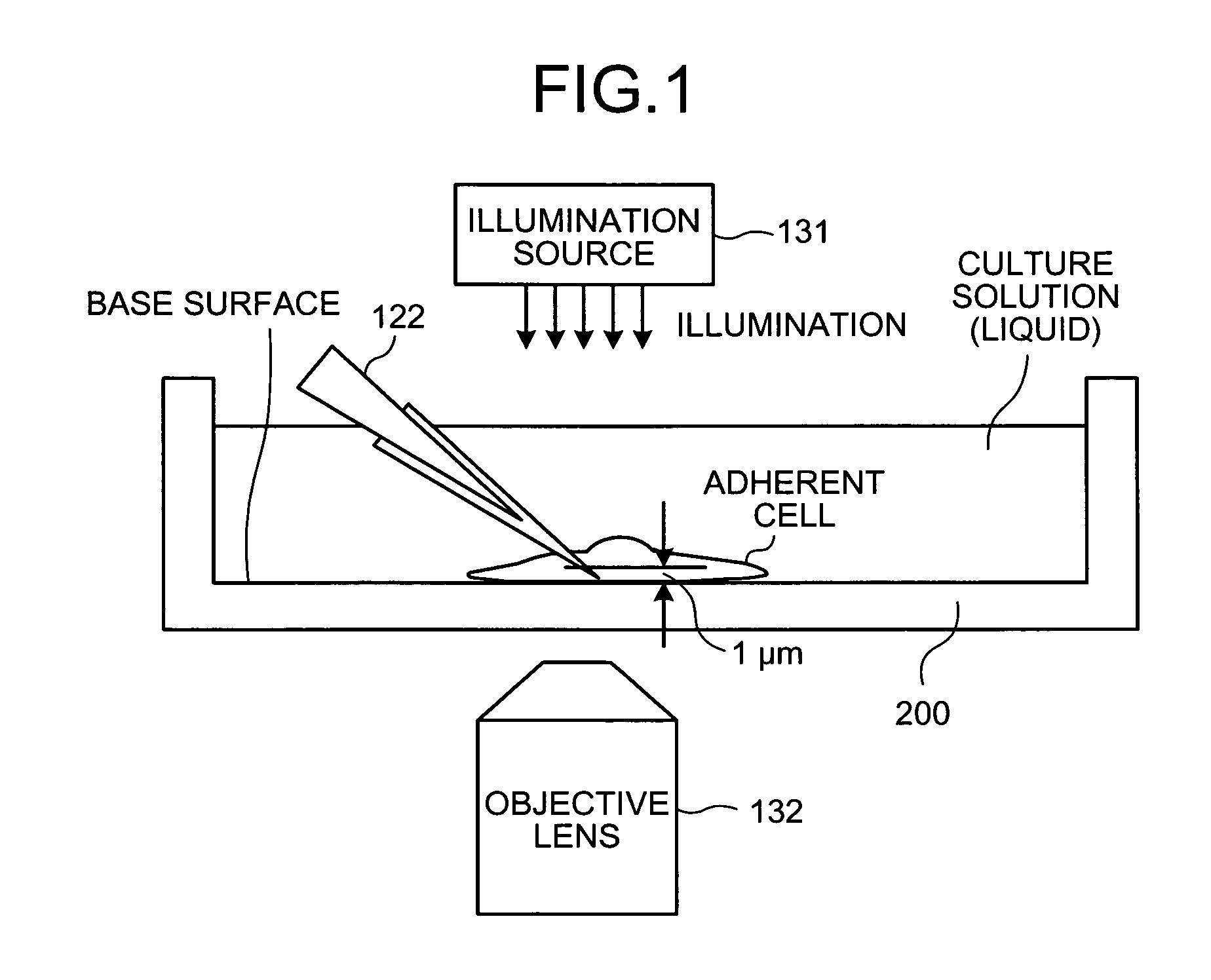
[0041]FIG. 1 is a schematic for explaining the technique of microinjection into an adherent cell. An adherent cell is a cell that has a nature of adhering to other cells and, by concentration of same kind of cells, constitutes a part of a living organism. Thus, an adherent cell has the nature opposite to that of a non-adherent cell, or a floating cell, such as a red blood cell, which does not have the nature of adherence and functions floating alone.

[0042]As shown in FIG. 1, when performing microinjection into an adherent cell, the adherent cell is placed on the bottom surface of ...


PUM


Abstract

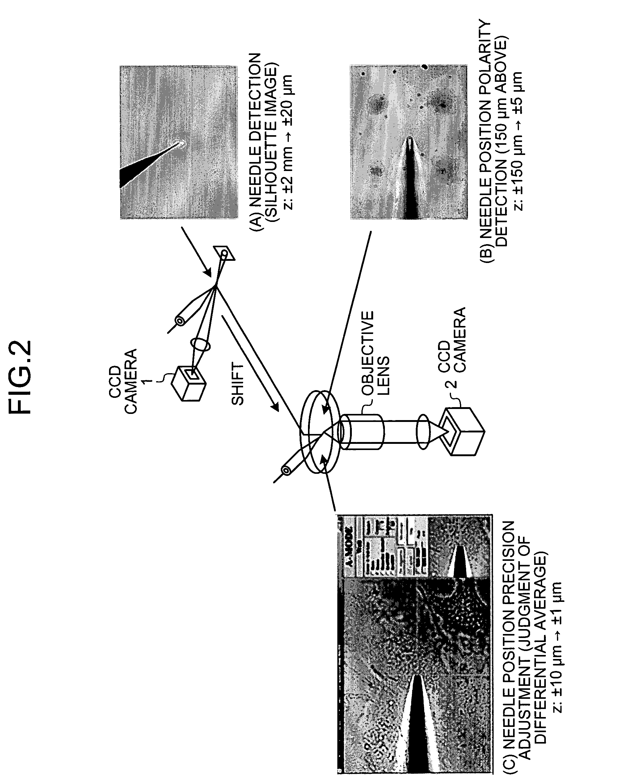
A microinjection apparatus of the present invention includes a needle-position polarity detecting unit that detects a position of the needle in the vertical direction at which a value of a differential aggregate distribution becomes the maximum in the situation in which a shape of the leading edge of the needle at a focal position narrows at the right. Moreover, a differential-average determining unit, based on a differential average of an image near the position detected by the needle-position polarity detecting unit, determines the lowest allowable position of the needle, which is a position at which a differential average exceeds a predetermined threshold.

Description

CROSS REFERENCE TO RELATED APPLICATIONS[0001]This application claims the benefit under 35 U.S.C. Section 119 of Japanese Patent Application No. 2006-206963, filed Jul. 28, 2006, which is hereby incorporated by reference in its entirety into this application.BACKGROUND OF THE INVENTION[0002]1. Field of the Invention[0003]The present invention generally relates to a technology for injecting an object into the cell with a needle. The present invention specifically relates to determining an operation start position of the needle.[0004]2. Description of the Related Art[0005]A study of an alteration of genetic information of a cell by running a microscopic needle into the cell and injecting a gene (microinjection), using a microscope clarifies a role of the gene and permits a tailor-made medicine of conducting gene treatment in accordance with individual genetic characteristics. Such study has made it possible to cure illness attributable to genetic causes that have heretofore been incura...

Claims


Application Information

Patent Timeline
Patent Type & Authority Patents(United States)
IPC IPC(8): G06K9/34
CPCG01N35/1009C12M35/00G02B21/241G02B21/32
Inventor ANDO, MORITOSHIYOUOKU, SACHIHIRO
Owner FUJITSU LTD
Learn More