Method and apparatus for joint source-channel map decoding

Inactive Publication Date: 2011-02-01
QUALCOMM INC
View PDF9 Cites 55 Cited by
  • Summary
  • Abstract
  • Description
  • Claims
  • Application Information

AI Technical Summary

Benefits of technology

[0015]A method and apparatus for digital communication is described that offers improved error correcting capabilities at a decoder, such as at a mobile device. Noisy data received at the mobile device is demodulated and sent to a decoder in the physical layer, such as a concatenated decoder. After decoding, both correctly received symbols and incorrectly received symbols (containing on

Problems solved by technology

However, factors such as limited transmit power, limited bandwidth and multi-path fading continue to restrict the data rates handled by practical systems.
In multimedia communications, particularly in error-prone environments, error resilience of the transmitted media is critical in providing the desired quality of service because errors in even a single decoded value can lead to decoding artifacts propagating spatially and temporally.
Various encoding measures have been used to minimize errors while maintaining a necessary data rate, however all of these techniques suffer from problems with errors arriving at the decoder side.
This is because the common transport protocols do not deliver corrupted data to the source decoder.
Despite its tremendous benefits to compression efficiency, entropy coding also complicates the decoding process.
The ambiguity around how many bits to consume for the next symbol in a bitstream, i.e. in an entropy coded representation of the output of an information source, is an obvious complication for a decoder.
However, much more importantly, in case of errors in the bitstream, the use of variable size codewords in conjunction with flipped bits (due to errors) will frequently result in the emulation of an incorrect codeword length and as a result the parsing/decoding process will loose its synchronization with the bitstream, i.e., correct identification of codeword boundaries and hence correct interpretation of the bitstream will start failing.
Assume a decoder implementing a basic level of error detection measures encounters a problem in decoding a bitstream and loses syncronization.
This will typically induce data loss to an extent much beyond the corruption that triggered the data los

Method used


Image

  • Method and apparatus for joint source-channel map decoding
  • Method and apparatus for joint source-channel map decoding
  • Method and apparatus for joint source-channel map decoding

Examples


Embodiment Construction

the correct value of the incorrectly received symbol.

BRIEF DESCRIPTION OF THE DRAWINGS

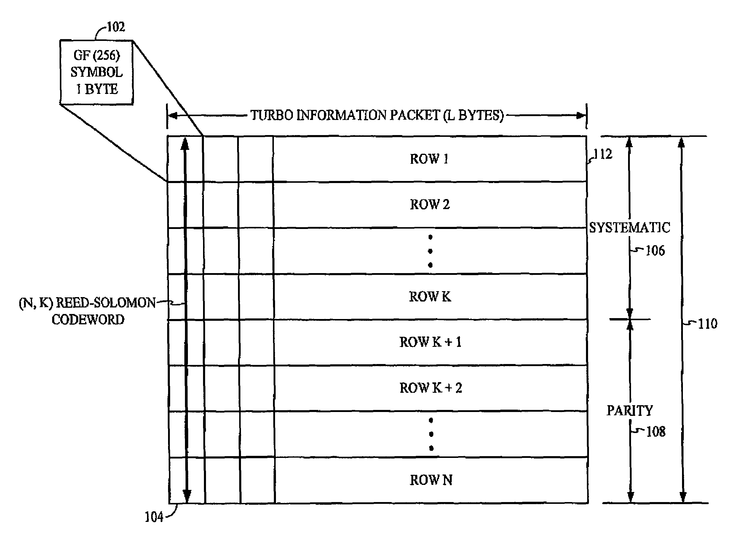
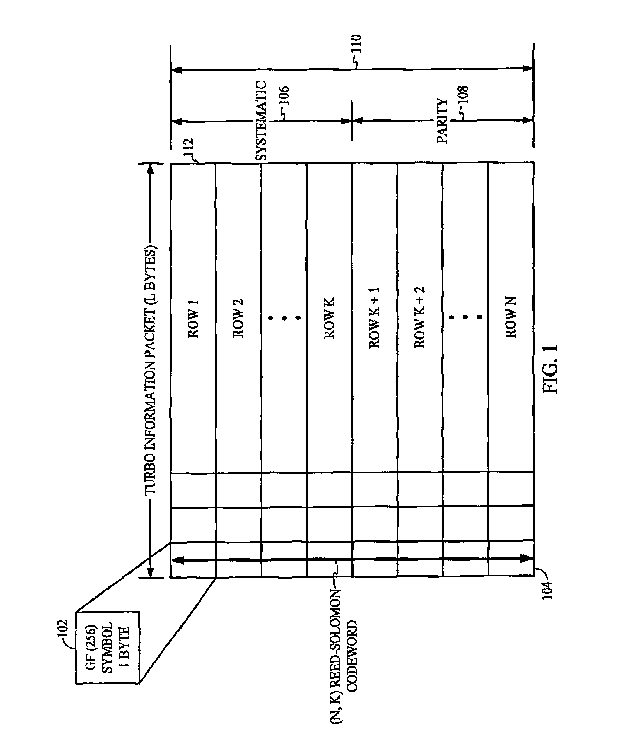
[0017]FIG. 1 is one example of symbols output from a source coder and formatted into a code block for Reed Solomon erasure coding followed by Turbo coding;

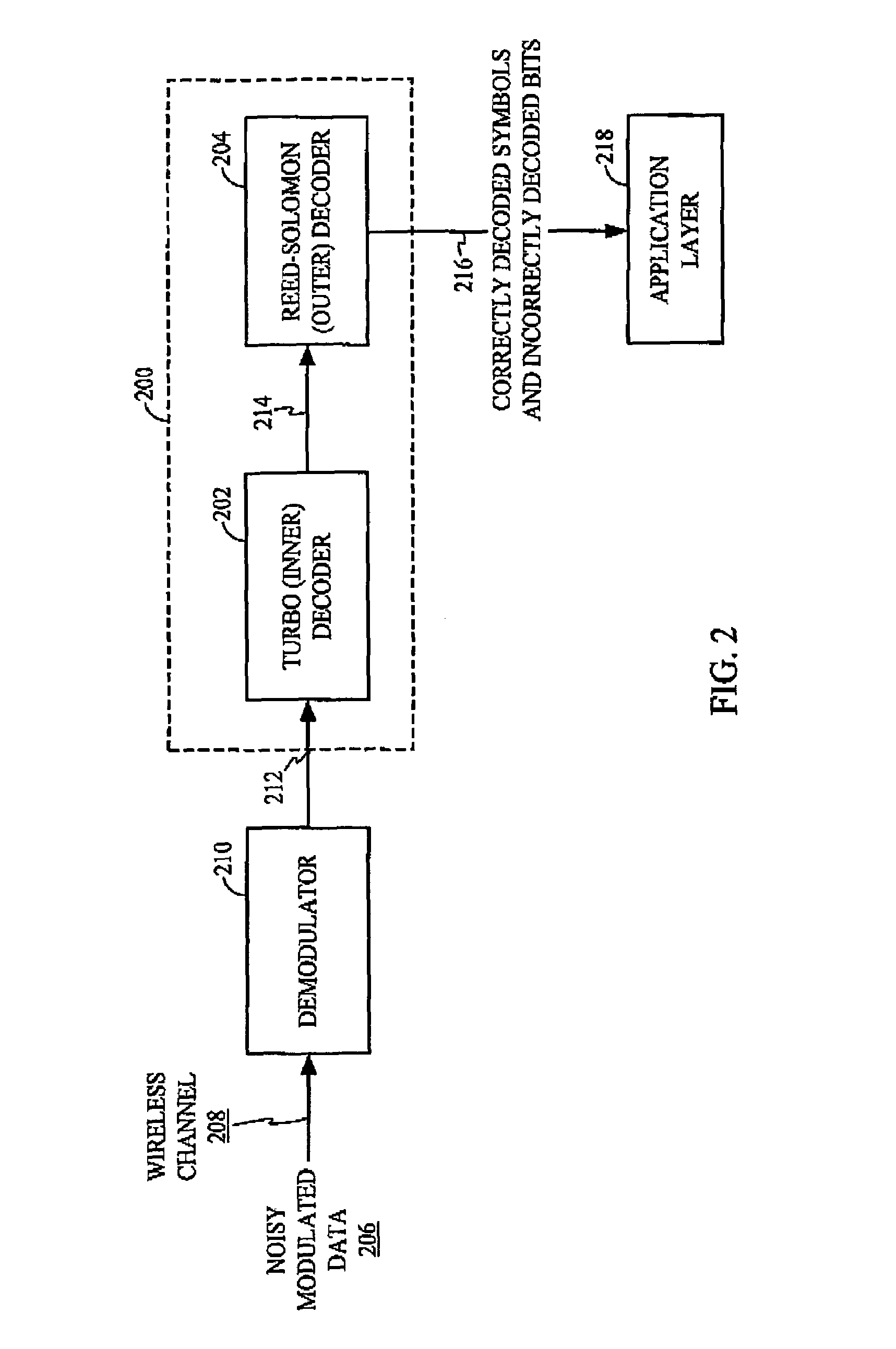
[0018]FIG. 2 is one example of a concatenated Turbo / Reed-Solomon decoding scheme;

[0019]FIG. 3 is one example of an illustration of neighboring 4×4 blocks providing correlating data for a corrupt block;

[0020]FIG. 4 is one example of a block diagram of a joint source-channel MAP entropy decoder;

[0021]FIG. 5 is one example of an illustration of a sequence of frames; and

[0022]FIG. 6 is one example of a flow diagram for a method of joint source-channel MAP entropy decoding.

DETAILED DESCRIPTION

[0023]In the following description, specific details are given to provide a thorough understanding of the embodiments described. However, it will be understood by one of ordinary skill in the art that the embodiments may be practiced without these specific detail...


PUM


Abstract

A method for error correction that includes receiving a bitstream, the bitstream comprising one or more bits, determining if the bitstream has one or more corrupt bits, determining one or more hypotheses representing an error pattern, and assigning a probability to each of the hypotheses, wherein the probability is determined based on one or more reference data.

Description

CLAIM OF PRIORITY UNDER 35 U.S.C. §119[0001]The present Application for Patent claims priority to Provisional Application No. 60 / 569,400 entitled “Method and Apparatus for Joint Source-Channel MAP VLC” filed May 6, 2004, and assigned to the assignee hereof and hereby expressly incorporated by reference herein.BACKGROUND[0002]1. Field[0003]The invention relates to digital communications and, more particularly, to channel and source decoding.[0004]2. Background[0005]The demands of higher data rates and higher quality of service in mobile communication systems is growing rapidly. However, factors such as limited transmit power, limited bandwidth and multi-path fading continue to restrict the data rates handled by practical systems. In multimedia communications, particularly in error-prone environments, error resilience of the transmitted media is critical in providing the desired quality of service because errors in even a single decoded value can lead to decoding artifacts propagating...

Claims


Application Information

Patent Timeline
IPC IPC(8): H03M13/00H03M7/40H03M13/29H03M13/45H04L1/00H04N19/89H04N19/895
CPCH03M13/2927H03M13/293H03M13/2936H03M13/2957H03M13/3916H03M13/45H03M13/63H03M13/6312H03M13/6318H04L1/0045H04L1/0055H04L1/0057H04L1/0065H04L1/0066
Inventor OGUZ, SEYFULLAH HALITRAVEENDRAN, VIJAYALAKSHUMI R.
Owner QUALCOMM INC
Why Eureka
Try Eureka