Repetitive fence for cross-cutting materials

a cross-cutting material and fence technology, applied in the field of repetitive fences, can solve the problems of increasing the number of adjustments, exacerbated disadvantages, and inability to provide such automated mechanisms in a cost-effective manner for homeowners utilizing woodworking tools such as table saws, sliding radial arm saws, etc., and achieve the effect of reducing the number of adjustments

Inactive Publication Date: 2011-02-08
WISE ROBERT W
View PDF14 Cites 12 Cited by
  • Summary
  • Abstract
  • Description
  • Claims
  • Application Information

AI Technical Summary

Benefits of technology

[0006]It is therefore an object of the present invention to provide for a repetitive cross-cut fence which minimizes the number of adjustments which are necessary for operation of the fence for a typical job.
[0007]It is a further object of the present invention to provide for a repetitive cross-cut fence which is easily adjustable for a variety of various cross-cut lengths while minimizing user error.
[0008]It is yet another object of the present invention to provide for a repetitive cross-cut fence which is easily readable and settable by a user.

Problems solved by technology

Homeowners utilizing woodworking tools such as table saws, miter saws (compound, sliding) radial arm saws, and the like cannot be provided with such automated mechanisms in a cost effective manner.
As a consequence, woodworkers have adopted the motto,“measure twice, cut once.” Thus, it is acknowledged that measuring a proper cutting dimension on a work piece is a source of error for a home craftsman utilizing a cutting tool which does not have automatic means for positioning the work piece with respect to the cutting tool or vice versa.
This disadvantage is exacerbated when the various cut dimensions may not be known in advance during a planning stage.
If a standard conventional manual repetitive fence is used, a great deal of organizational forethought is necessary to minimize adjustment of the fence throughout completion of a typical job.

Method used


Image

  • Repetitive fence for cross-cutting materials
  • Repetitive fence for cross-cutting materials
  • Repetitive fence for cross-cutting materials

Examples


Embodiment Construction

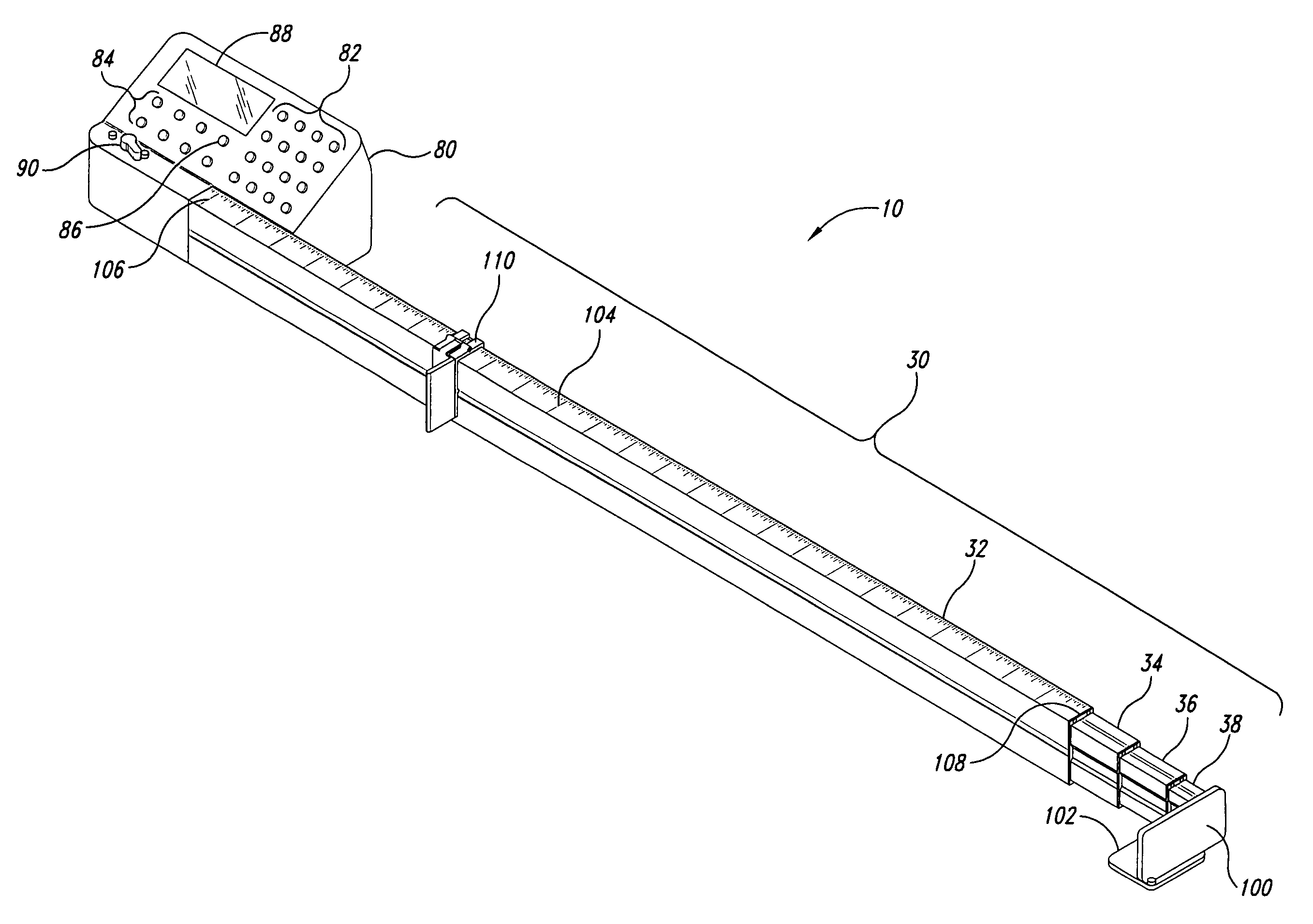
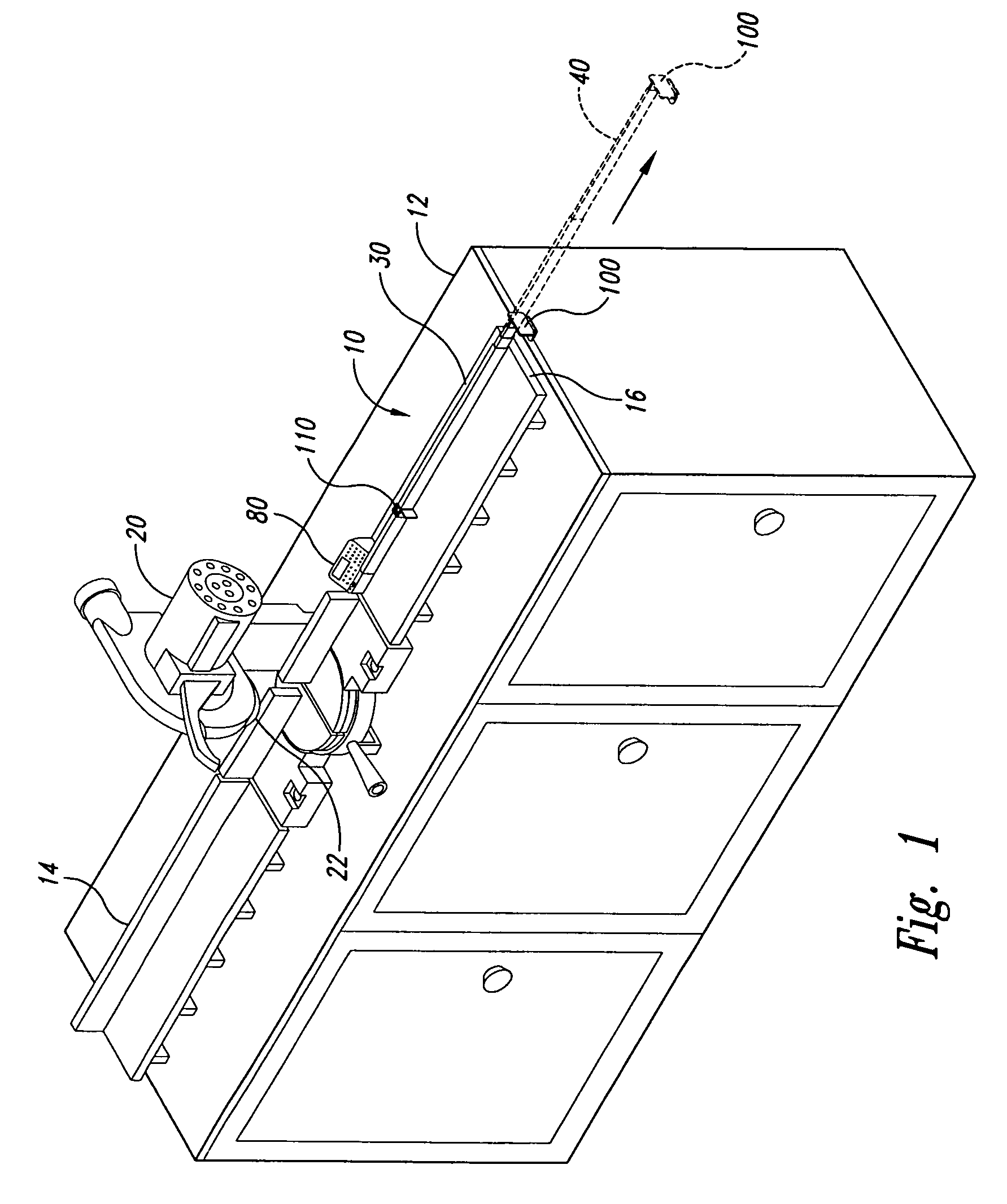
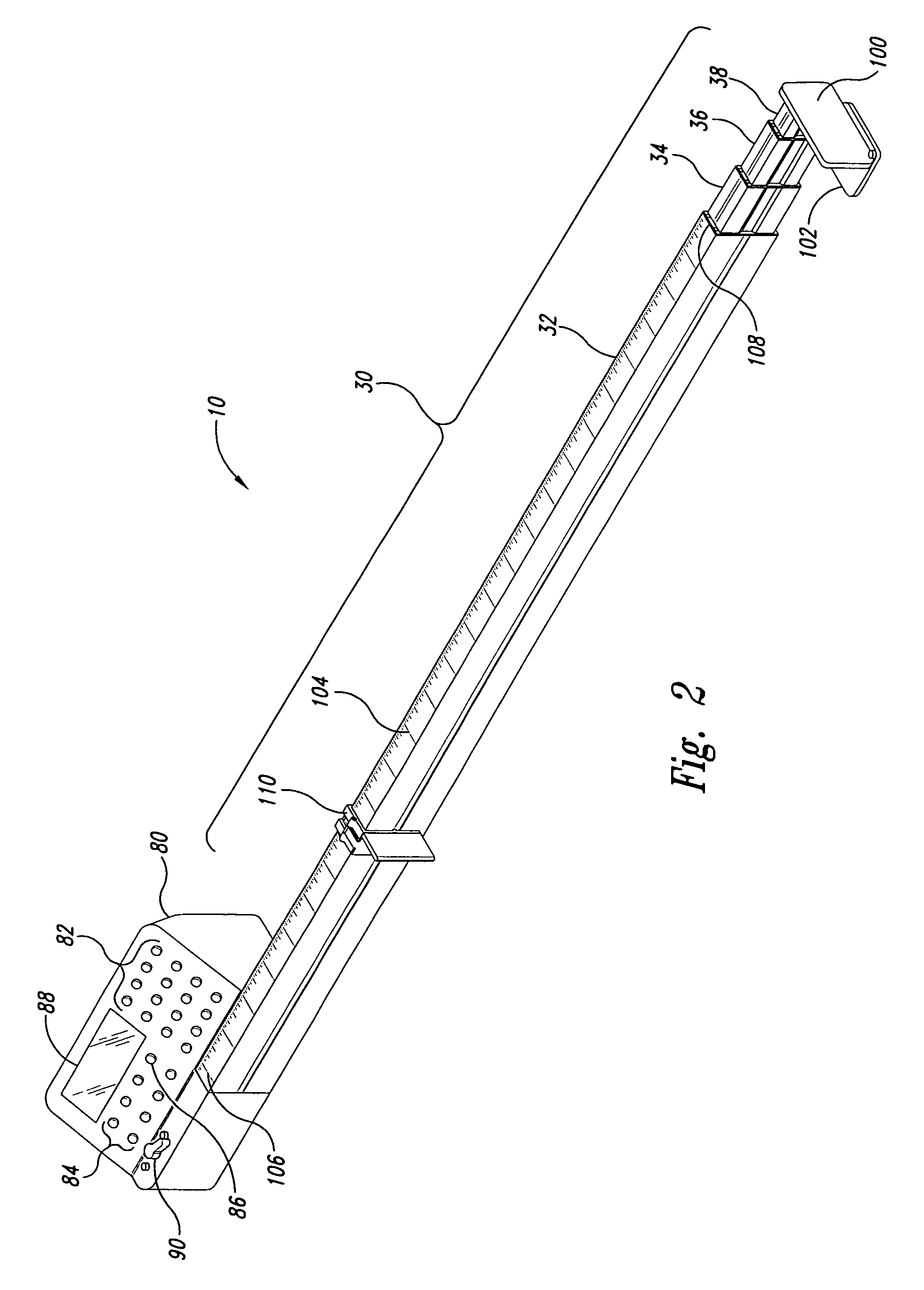
[0020]A first embodiment of a repetitive fence for cross-cutting materials, such as lumber in accordance with the principals of the invention is generally indicated at reference 10 in FIGS. 1 and 2 wherein numbered elements in the figures correspond to like numbered elements herein. FIG. 1 shows the invention in use in a typical home workshop environment in connection with a work bench 12 having an in-feed table 14, and a spaced apart out-feed table 16. A circular chop saw 20 having a motor driven rotatable blade 22 is positioned between the tables 14, 16. The saw 20 is illustrated by way of example only so as to represent a cross-cutting saw which may be of a variety of types including circular table saws, radial arm saws, miter saws (compound, sliding) chop saws (rotary, band, reciprocating) or any other type of cutting or milling device which may work against the long dimension of a work piece, such as standard dimension lumber. The repetitive fence 10 permits a user (not shown) ...


PUM

PropertyMeasurementUnit
distanceaaaaaaaaaa
lengthaaaaaaaaaa
lengthaaaaaaaaaa

Abstract

A repetitive fence utilizes a plurality of telescoping arms driven by a metal tape of the tape measure type to position a stop member at a desired location from a saw blade. A user can position a work piece, such as board lumber against the stop member to repeatedly position the work piece at a desired cut dimension with respect to a saw blade. The repetitive fence preferably employs a plurality of telescoping arms to position the stop member at the desired location, and an electronic read-out provided to indicate to the user the position of the stop member with respect to the saw blade. The telescoping arms can be motivated by electronic devices, such as an electric motor, or by a manual crank.

Description

TECHNICAL FIELD[0001]The invention relates to repetitive fences for use with cross-cutting saws. More specifically, the invention relates to a repetitive fence for attachment to a cross-cut saw, such as a miter saw, chop saw, radial arm saw, table saw, or the like with reference to a blade of the saw.BACKGROUND OF THE INVENTION[0002]Industrial machine tools such as numerically controlled milling machines and the like have been provided with adjustable stages, chucks, and other devices for holding a work piece with respect to a working tool such as a drill press, milling head, band saw, or the like. Typically, such devices hold the work piece in place while the working tool itself moves with respect to the work piece. More sophisticated machinery also permits the automatic feeding of material stock (e.g., bar stock) to the working tool for placement with respect thereto. Such systems employ feedback mechanisms to assure that the working material is actually in place, and is properly ...

Claims


Application Information

Patent Timeline
Patent Type & Authority Patents(United States)
IPC IPC(8): B26D7/01B26D7/27
CPCB27B27/02B27B27/04B27B27/10Y10T83/7613Y10T83/856
Inventor WISE, ROBERT W.
Owner WISE ROBERT W
Why Eureka
Try Eureka