Inkjet recording apparatus with plural heads and suction unit

a technology of suction unit and recording apparatus, which is applied in the direction of printing, etc., can solve the problems of visible image defect, inability to wipe, suction or spitting head surface, and prominent failure of nozzle ejection, so as to achieve high-speed formation of high-quality images and high-quality images

Active Publication Date: 2011-02-08
FUJIFILM CORP
View PDF13 Cites 0 Cited by
  • Summary
  • Abstract
  • Description
  • Claims
  • Application Information

AI Technical Summary

Benefits of technology

[0010]The present invention has been made under these circumstances and an object of the present invention is to provide an inkjet recording apparatus ensuring that ink adhered to the nozzle plate during image drawing can be removed and a high-quality image can be formed at a high speed.
[0012]According to the inkjet head recording apparatus of this construction, since ink suction means having a suction port arranged every each inkjet head and disposed in the vicinity of the nozzle thereof is provided, adhesion of unnecessary ink to the inkjet head including the periphery of nozzle can be suppressed and at the same time, the ink adhered to the inkjet head can be eliminated, so that is a high-quality image can be formed by preventing misdirected ejection, no ejection, change of ejection amount and ink dripping.
[0015]According to the inkjet head recording apparatus of this construction, since the suction port is disposed in the head holder to run in parallel with the line of nozzles, the straight ejection property of ink is not affected and air in the vicinity of the nozzle can be suctioned while ejecting the ink from the nozzle, so that a high-quality image can be formed by suctioning and eliminating the ink adhered to the nozzle plate and at the same time, suctioning the ink mist.
[0017]According to the inkjet head recording apparatus of this construction, since the suction port is disposed between the head holder and the head to run in parallel with the line of nozzles, the suction port can be disposed in the vicinity of the nozzle by a simple mechanism and the ink adhered to the nozzle plate can be suctioned and eliminated or the ink mist can be suctioned. Furthermore, when the lower surface of the head holder is projected from the lower surface of the head to form a wall on the side opposite the nozzle with respect to the suction port, the air on the nozzle side can be efficiently suctioned and the ink mist or ink adhered to the nozzle plate can be unfailingly suctioned and eliminated.
[0019]According to the inkjet head recording apparatus of this construction, since the suction port is provided integrally with the nozzle to run in parallel with the line of nozzles, the suction port can be disposed very close to the nozzle and the ink mist generated upon ejection of ink from the nozzle can be immediately suctioned and recovered even by a weak suction power and prevented from adhering to the nozzle plate. The ink adhered to the nozzle plate can also be suctioned and removed, whereby a high-quality image can be formed.
[0020]According to the present invention, an inkjet recording apparatus capable of removing ink adhered to the nozzle plate during image drawing and performing high-speed formation of a high-quality image can be provided.

Problems solved by technology

The inkjet head has a large number of nozzles and when an ejection failure of the nozzle is generated, this is visible as an image defect.
The ejection failure of nozzle occurs prominently in particular when ejection from the nozzles is continued for a certain period of time.
However, the recording devices described in JP-A-2005-14560, JP-A-2005-20576 G and JP-A-2005-199465 all are a recording apparatus employing a system such that the recording is performed by ejecting an ink while transferring an inkjet head in the direction perpendicular to the conveyance direction of a recording medium, and in the case of an inkjet recording apparatus employing a single pass system using a full line head of recording an image by only once passing a recording medium beneath the inkjet head, the wiping, suctioning or spitting of head surface cannot be performed, because the head is always located in the recording region.
In the recording apparatus described in JP-A-2005-14560, volatile substances adhered to the inkjet head are removed by generating an air flow in the vicinity of the inkjet head with use of air-blowing or suctioning means disposed apart from the inkjet head, but because of distant location from the head, the effect of removing nonvolatile substances is insufficient.
Nonvolatile substances are gradually accumulated in the inkjet head during a long-term use and cause an ejection failure of nozzle.
When ink mist is removed by suctioning air in the vicinity of nozzles from somewhat distant position or by blowing and suctioning air as in the recording apparatus described in JP-A-2005-205766 and JP-A-2005-199465, this sometimes incurs deterioration of the straight ejection property of ink and reduction in the image quality.
Also, it is difficult to completely prevent the ink mist from adhering to the nozzle plate, and when ink mist is once attached to the nozzle plate, there is no effective means to solve the ejection failure of nozzle, for example, the ink adhered during image drawing cannot be removed.

Method used


Image

  • Inkjet recording apparatus with plural heads and suction unit
  • Inkjet recording apparatus with plural heads and suction unit
  • Inkjet recording apparatus with plural heads and suction unit

Examples


first embodiment

[0030]Each embodiment of the present invention is described in detail below by referring to the drawings.

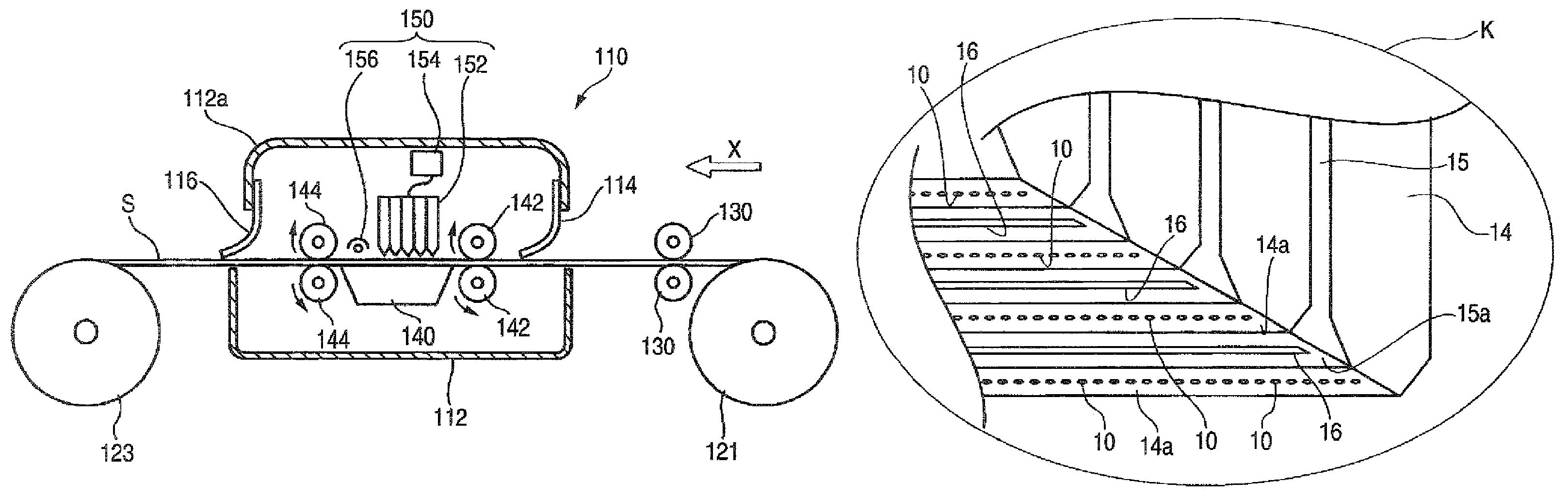
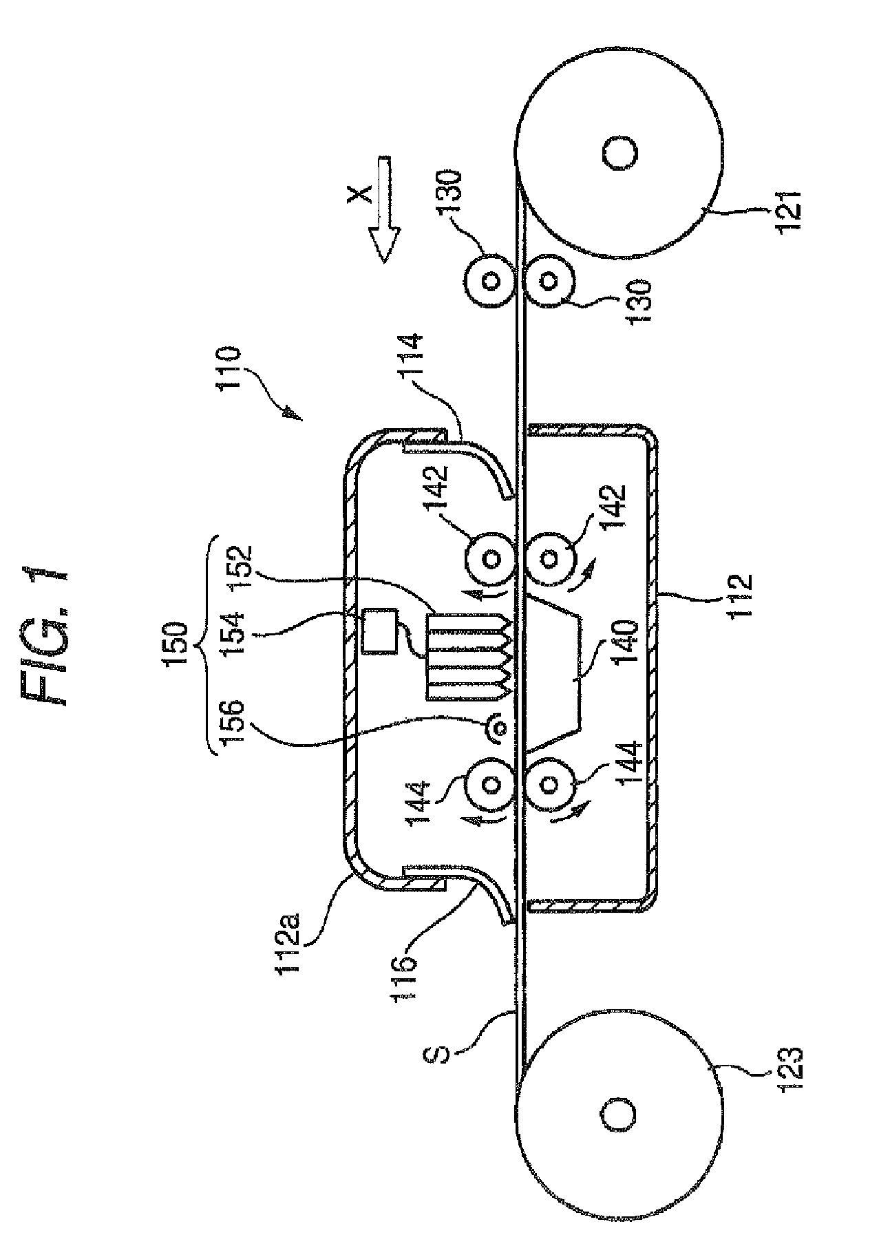
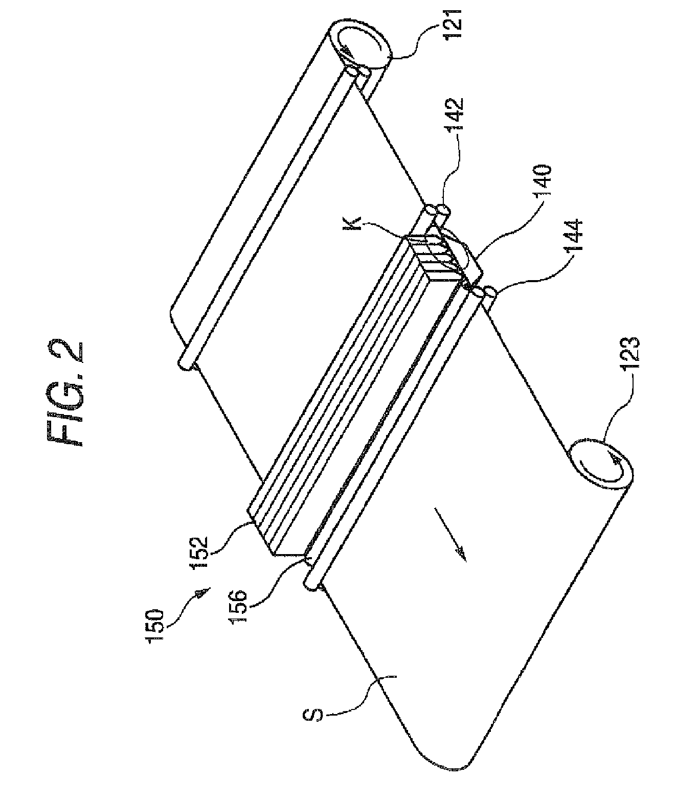
[0031]FIG. 1 is a schematic constitutional view showing one embodiment of the inkjet recording apparatus for practicing an active energy curing-type inkjet recording method, out of the inkjet recording apparatuses according to the present invention, and FIG. 2 is an enlarged perspective view showing the image recording part using an inkjet head in the active energy curing-type inkjet recording apparatus shown in FIG. 1.

[0032]The active energy curing-type inkjet recording apparatus 110 of this embodiment uses, as the active energy curable ink, a UV curable ink which is cured by the ultraviolet irradiation.

[0033]In FIG. 1, the active energy curing-type inkjet recording apparatus 110 has a cage 112, and a recording medium S wound around a roll 121 on the delivery side is rolled out by conveyance rollers 130 and after passing through a flexible light-shielding door 114, conveyed into...

second embodiment

[0052]The head unit of the second embodiment is described below by referring to FIGS. 6 and 7. In the head unit of the second embodiment, the suction port is disposed between the head holder and the inkjet head to run in parallel with the line of nozzles. FIG. 6 is a perspective view seeing the head unit of the second embodiment from below, and FIG. 7 is a partial sectional view showing one head holder in FIG. 6 and inkjet heads sandwiching the head holder.

[0053]Incidentally, the second embodiment is different only in the suction port construction of the head unit and since other portions are the same as those of the inkjet recording apparatus 110 of the first embodiment described above, only the head unit is shown.

[0054]The head unit 31 of the second embodiment comprises an inkjet head 14 and a head holder 35 for fixing the inkjet head 14. In the inkjet head 14, similarly to the inkjet head 14 of the first embodiment, a large number of nozzles 10 are arrayed at predetermined interv...

third embodiment

[0061]The head unit of the third embodiment is described below by referring to FIG. 8. In the head unit of the third embodiment, the nozzles and the suction port disposed in parallel with the line of nozzles are integrally arranged in the head unit. FIG. 7 is a perspective view seeing the head unit of the third embodiment from below.

[0062]Incidentally, since the third embodiment is the same as the inkjet recording apparatus 100 of the first embodiment described above except that the suction port and the nozzles are integrally arranged in the head unit, only the head unit is shown.

[0063]As shown in FIG. 8, in the head unit 41 of the third embodiment, similarly to the inkjet head 14 of the first embodiment, a large number of nozzles 10 are arrayed at predetermined intervals and connected to an ink tank (not shown) for reserving a functional liquid material (ink).

[0064]On the lower surface 14a of the inkjet head 14, before and after the nozzles 10 (in the direction orthogonal to the ar...


PUM


Abstract

An inkjet recording apparatus includes: a plurality of inkjet heads having nozzles ejecting a functional liquid material on a recording medium; a head holder fixing the plurality of inkjet heads at predetermined intervals; and an ink suction unit that has a suction port disposed in the vicinity of the nozzles thereof.

Description

BACKGROUND OF THE INVENTION[0001]1. Field of the Invention[0002]The present invention relates to an inkjet recording apparatus of ejecting a functional liquid material such as ink drop on a recording medium to record an image (including letters, hereinafter the same). More specifically, the present invention relates to an inkjet recording apparatus equipped with a head unit having a mechanism of suctioning ink mist generated at the ejection of an ink drop and suctioning also ink adhered to a nozzle plate (inkjet head).[0003]2. Background Art[0004]The inkjet recording apparatus where a functional material (functional liquid material) curable with energy such as ultraviolet ray and electron beam is ejected on a recording medium from nozzles of an inkjet head and the functional material is cured by the irradiation of energy, thereby performing the image formation, has many characteristic features, for example, this system is environment-friendly, high-speed recording can be made on var...

Claims


Application Information

Patent Timeline
Patent Type & Authority Patents(United States)
IPC IPC(8): B41J2/165
CPCB41J2/1707B41J2/17563
Inventor HIRATO, KATSUYUKI
Owner FUJIFILM CORP
Why Eureka
Try Eureka