Projection apparatus and method for pepper's ghost illusion

a projection apparatus and ghost technology, applied in the field of projection apparatus and method of pepper's ghost illusion, can solve the problems of significant levels of ambient light reflection from the screen detracting from the strength of the reflected image over the background, unwanted light hitting the projection surface, and affecting the viewed quality of the image projected onto the foil, so as to enhance the illusion of the projected image disappearing, reduce the contrast ratio of the projected image, and enhance the effect of the three-dimensional effect of the projected image interaction

Active Publication Date: 2011-02-08
ANAKANDO LTD +1
View PDF22 Cites 21 Cited by
  • Summary
  • Abstract
  • Description
  • Claims
  • Application Information

AI Technical Summary

Benefits of technology

[0023]The mask can be used to make the illusion of an article disappearing and reappearing behind a prop that is placed upon a stage, either behind or in front of the screen.
[0024]The apparatus may comprise a light source arranged to selectively illuminate an area of stage comprising the prop. The light source may be a white light source Lighting the prop causes the prop to become more visible and better defined against the dark, typically black, background. This enhances the three dimensional effect of the projected image interacting with the prop.
[0025]Also directing bright light upon the prop serves to reduce the contrast ratio of the projected image upon the prop, which typically remains slightly visible even when a mask is used in the prop's shadow upon the reflective member, thus enhancing the illusion of the projected image disappearing behind the prop.

Problems solved by technology

However, current image projection apparatus' do have a number of problems associated with them, for example, mounting of the foil can prove difficult which in turn leads to uneven tensioning of the foil and wrinkles upon the foil, that impair the viewed quality of the image projected onto the foil.
In circumstances where the presenter may be unable to control high levels of ambient light forward of the foil, e.g. from an auditorium at a trade show, the high level of ambient light results in significant levels of reflection of the ambient light from the screen detracting from the strength of the reflected image over the background.
However, the use of a bright projector results in unwanted light hitting the projection surface and reflecting through the foil to create a milky hue upon the stage and around the area where the reflected image appears.
Another problem with current image projection apparatus is that projectors used with such apparatus are very powerful, typically 8,000 to 27,000 lumens and consequently project a significant amount of light into areas of an image where there is no object within the image.
This is an inherent feature of projectors and results in low contrast ratios which leads to a milky hue spread over the part of the film where the projector is creating an image when the projector is switched on.
The milky hue is clearly undesirable as it detracts from the viewer's perception that there is no screen present.
A further problem associated with some projectors is the “keystone” effect, in which distorted, typically elongated, images (up and down) occur due to angled projection.
However, older, less-expensive or even some specialist High Definition projectors do not employ such digital keystone correction and are therefore difficult to configure for use with current image projection apparatus.
High definition (HD) projectors do not offer keystone adjustment because when keystone correction is attempted in conjunction with the increased number of pixels about an image's edge causes the pixels about the edge of the image to appear ‘crunched’.
Additionally, when processing moving images HD projectors compromise projector processing speed.
In general, it can be said that the use of electronic keystone correction to alter a video image will result in the degradation of picture quality compared to an image which is not subject to such a process.
Additionally, current systems do not allow for the projected image to apparently disappear and re-appear from behind a solid 3D object placed upon the stage, as the screen lies in front of the presenter and closest to the viewing audience.

Method used


Image

  • Projection apparatus and method for pepper's ghost illusion
  • Projection apparatus and method for pepper's ghost illusion
  • Projection apparatus and method for pepper's ghost illusion

Examples


Embodiment Construction

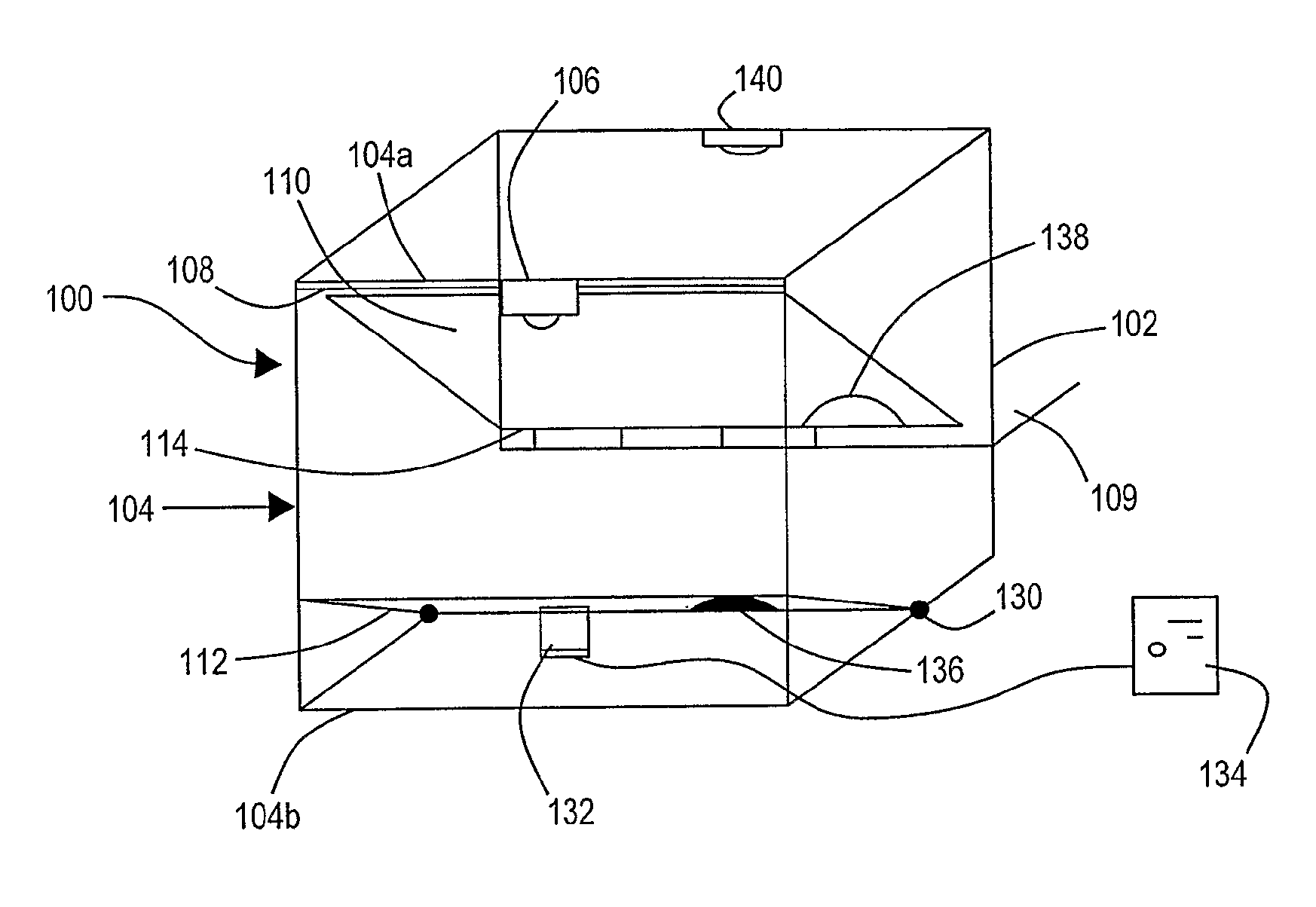
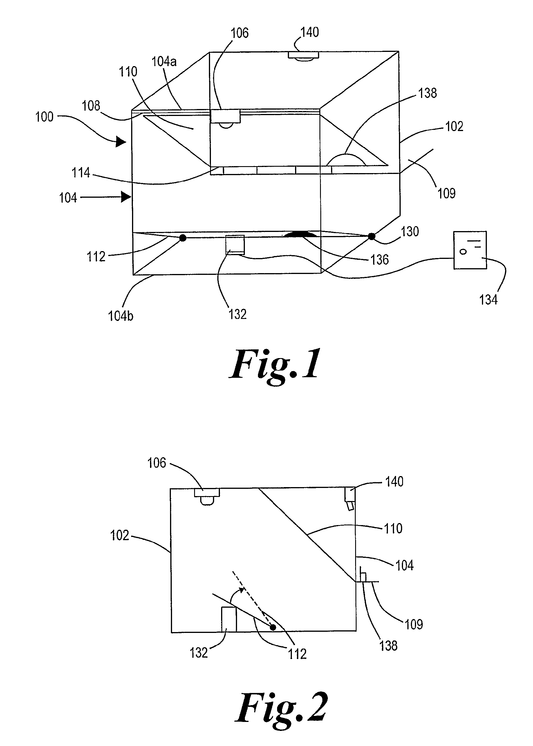
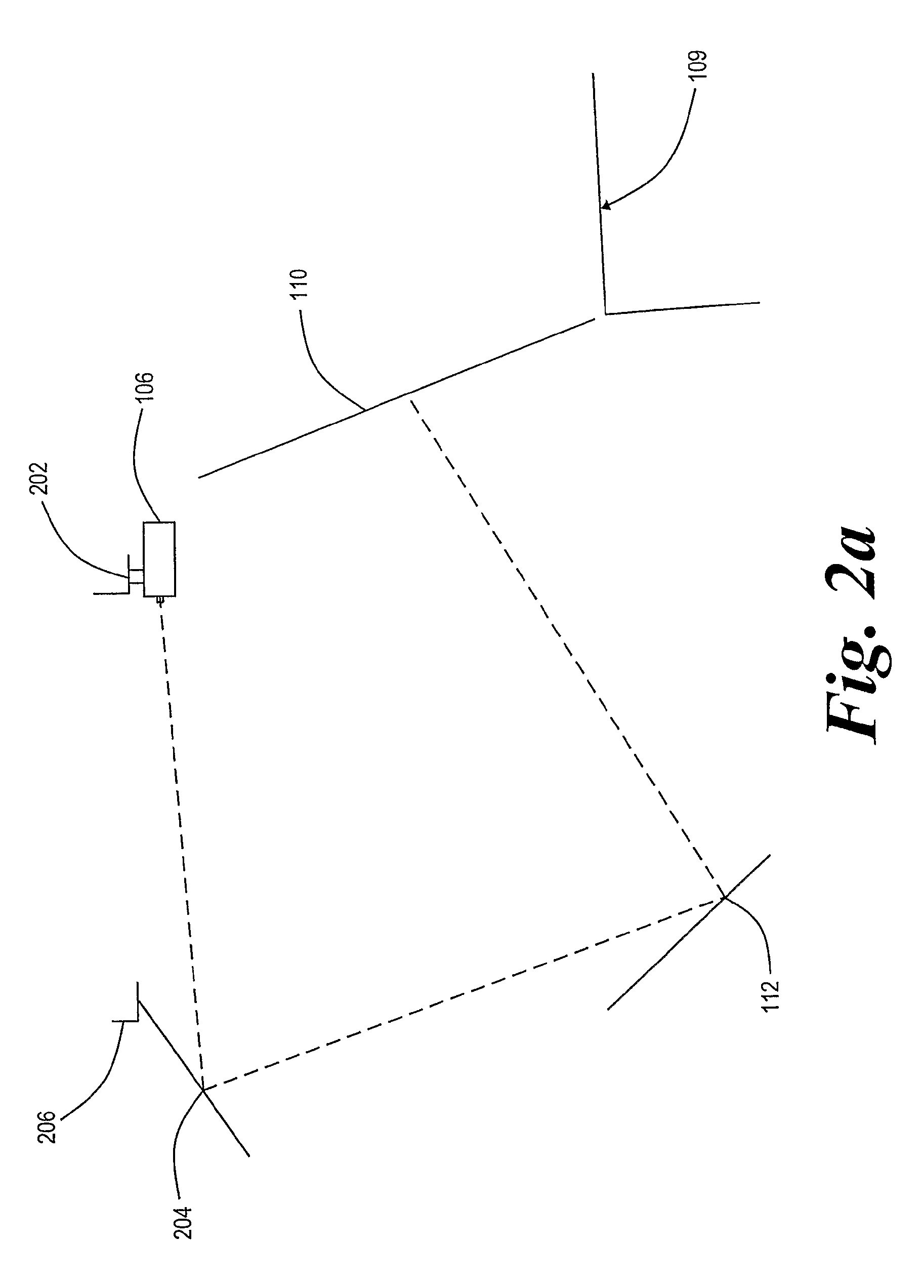
[0049]Referring now to FIGS. 1, 2 and 4, a projection apparatus 100 comprises a box frame 102 formed of trusses 104, a projector 106, a support frame 108, a screen 110 held within the support frame 108 and a grey pigmented reflective board 112.

[0050]The projector 106 depends from a front upper cross-piece truss 104a of the box frame 102. The board 112 lies below the projector 106 at the base of the box frame 102. The screen 110, is inclined at approximately 45° to the horizontal and the front edge of the screen 110 is proximate the front upper cross-piece truss 104a of the box frame 102 and the rear edge of the screen is proximate a stage 109 that lies to the rear of the box frame 102.

[0051]The screen 110 is typically a polymeric foil, which can have a partially reflective coating upon a front face of the foil. The screen 110 is retained within the box frame 102 by means of tensioning straps 114 attached to the box frame 102, at the top and bottom edges of the screen 110. At a free ...


PUM


Abstract

An image projection apparatus (100) comprises a projector (106), a frame (108), and a partially transparent screen (110). The frame (108) retains the screen (110) under tension, such that the screen (110) is inclined at an angle with respect to a plane of emission of light from the projector (106). The screen (110) has a front surface arranged such that light emitted from the projector (106) is reflected therefrom. The projector (106) projects an image such that light forming the image impinges upon the screen (11) such that a virtual image is created from light reflected from the screen (110), the virtual image appearing to be located behind the screen (110).

Description

[0001]This invention relates to a projection apparatus and method. More particularly, but not exclusively, it relates to a projection apparatus arranged to project an image of an object upon an inclined, partially reflective, screen so as to give a false perception of depth and a method for constructing such an apparatus.BACKGROUND OF THE INVENTION[0002]The projection of an image upon a partially reflective screen such that is observable by a viewer positioned in front of the screen is known, the so-called “Peppers ghost” arrangement that is known form fairground shows.[0003]This has been applied to publicity and promotional displays where a presenter resides behind an inclined, partially reflective screen, typically a tensioned foil, onto which an image of, for example, a motor vehicle is projected, via at least one reflective surface, see for example EP 0799436. The location of the presenter behind the projected image has a number of inherent advantages over systems where the pres...

Claims


Application Information

Patent Timeline
Patent Type & Authority Patents(United States)
IPC IPC(8): G03B21/00A63J5/00A63G31/00G03B21/56G02B27/22A63J5/02A63J25/00A63J99/00G02B30/60G03B21/28
CPCA63J25/00G02B27/0018G02B27/24G03B21/28G02B27/2292G02B30/56A63J5/02G03B15/10G03B21/14G03B21/00G02B30/60
Inventor O'CONNELL, IANROCK, JAMES
Owner ANAKANDO LTD
Why Eureka
Try Eureka