Proximity sensor device and method with keyboard emulation

a proximity sensor and keyboard technology, applied in the field of electronic devices, can solve the problems of limiting the functionality of the proximity sensor device, preventing the proximity sensor device from being used for certain types of input during startup, and unable to meet the needs of users, etc., and achieve the effect of improving the usability of the devi

Inactive Publication Date: 2011-02-08
SYNAPTICS INC
View PDF8 Cites 5 Cited by
  • Summary
  • Abstract
  • Description
  • Claims
  • Application Information

AI Technical Summary

Benefits of technology

[0006]The embodiments of the present invention provide a proximity sensor device and method that facilitates improved device usability. Specifically, the proximity sensor device and method provide control functionality without requiring loading of a specialized piece of host software for the proximity sensor device. For example, the proximity sensor device can be used to provide a limited set of control functions prior to the specialized host software loading, and then switch to provide full range of functionality when the specialized host software has been loaded.

Problems solved by technology

One issue with some past proximity sensor devices is that their functionality commonly requires the loading of a specialized piece of host software, commonly referred to as a type of specialized device driver, on the electronic system before the proximity sensor device can provide input to the system.
For example, in a typical laptop computer system the proximity sensor device cannot be used for certain types of input until the operating system and the associated drivers have been loaded into the system.
This prevents the proximity sensor device from being used for certain types of input during startup or in cases where the specialized host software has failed to properly load.
This undesirably limits the functionality of proximity sensor device.

Method used


Image

  • Proximity sensor device and method with keyboard emulation
  • Proximity sensor device and method with keyboard emulation
  • Proximity sensor device and method with keyboard emulation

Examples


first embodiment

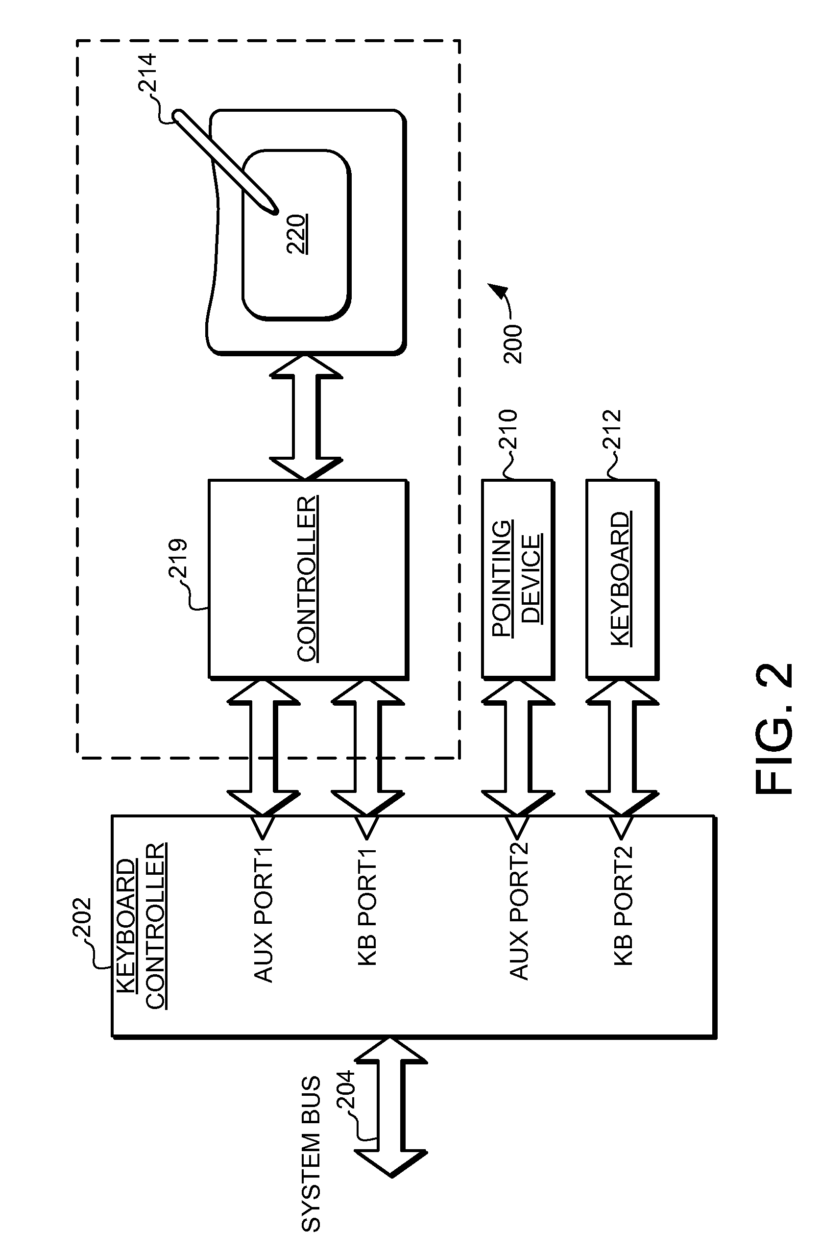
[0037]Turning now to FIG. 2, a proximity sensor device 200 is illustrated. The proximity sensor device 200 includes a controller 219 and a sensing region 220, where the proximity sensor device 200 is sensitive to the position of one or more input objects, such as a stylus 214. In the embodiment of FIG. 2, the proximity sensor device 200 is coupled to an electronic device through a keyboard controller 202, which is in turn coupled to a system bus 204 of the electronic device.

[0038]In the embodiment illustrated in FIG. 2, the keyboard controller 202 includes two keyboard ports (labeled KB PORT1 and KBPORT2) and two auxiliary ports (labeled AUX PORT1 and AUX PORT2). AUX PORT1 and KB PORT1 are coupled to the controller 219 in the proximity sensor device 200. AUX PORT2 is coupled to another pointing device 210, and KB PORT2 is coupled to a keyboard 212. This illustrates a suitable implementation for the proximity sensor device in a computer that also includes a keyboard and a pointing de...

second embodiment

[0043]Furthermore, in some applications both the simulated keyboard information and the object positional information can be provided through the same input port on keyboard controller. Turning now to FIG. 3, a proximity sensor device 300 is illustrated. The proximity sensor device 300 includes a controller 319 and a sensing region 320. Like the embodiment shown in FIG. 2, the proximity sensor device 300 is coupled to an electronic device through a keyboard controller 302, which is in turn coupled to a system bus. In the embodiment illustrated in FIG. 3, the keyboard controller 302 includes a dynamic port (labeled DYNAMIC PORT), a keyboard port (labeled KB PORT) and an auxiliary port (labeled AUX PORT). The dynamic port is coupled to the controller 319 in the proximity sensor device 300. AUX PORT is coupled to a pointing device 310, and KB PORT is coupled to a keyboard 312.

[0044]In this type of keyboard controller, the dynamic port is able to function as both a keyboard port, receiv...

third embodiment

[0049]In some applications the simulated keyboard information and the object positional information can be routed through the controller of another pointing device. Turning now to FIG. 4, a proximity sensor device 400 is illustrated. The proximity sensor device 400 includes a controller 419 and a sensing region 420. Unlike the previous embodiments, the proximity sensor device 400 is coupled to the keyboard controller 402 through an intermediate pointing device controller 408. The pointing device controller 408 thus serves as the controller for the pointing device sensor 406, as well as providing for the routing of data from the proximity sensor device 400. In the embodiment illustrated in FIG. 4, the keyboard controller 402 includes a keyboard port and an auxiliary port, and both of these ports are coupled to the pointing device controller 408.

[0050]In general, this type of implementation is particularly useful in applications where the keyboard controller has a limited number of au...


PUM


Abstract

A proximity sensor device and method is provided that facilitates improved device usability by providing a at least one control function prior to the specialized host software loading, and then switch to provide full range of functionality when the specialized host software has been loaded. In one embodiment, the proximity sensor device comprises a proximity sensor adapted to detect object presence and a controller configured to output simulated keyboard information and output object positional information. For example, when operating in a first mode prior to the specialized host software loading the controller outputs the simulated keyboard information that indicates a control function to a keyboard controller. Then, when operating in a second mode after the specialized host software has been loaded, the controller outputs object positional information to the keyboard controller. The object positional information can be used to provide a full range of user interface functions.

Description

FIELD OF THE INVENTION[0001]This invention generally relates to electronic devices, and more specifically relates to proximity sensor devices and using a proximity sensor device for producing user interface inputs.BACKGROUND OF THE INVENTION[0002]Proximity sensor devices (also commonly called touch pads or touch sensor devices) are widely used in a variety of electronic systems. A proximity sensor device typically includes a sensing region, often demarked by a surface, which uses capacitive, resistive, inductive, optical, acoustic and / or other technology to determine the presence, location and / or motion of one or more fingers, styli, and / or other objects. The proximity sensor device, together with finger(s) and / or other object(s), can be used to provide an input to the electronic system. For example, proximity sensor devices are used as input devices for larger computing systems, such as those found integral within notebook computers or peripheral to desktop computers. Proximity sen...

Claims


Application Information

Patent Timeline
Patent Type & Authority Patents(United States)
IPC IPC(8): G06F3/041G06F3/038
CPCG06F3/023G06F3/038
Inventor TRENT, JR., RAYMOND ALEXANDER
Owner SYNAPTICS INC
Why Eureka
Try Eureka