Additives for liquid-cooled inflators

a technology of additives and liquid-cooled inflators, which is applied in the field of additives for liquid-cooled inflators and liquid-cooled inflators, can solve the problems of increasing the cost and weight of an associated inflator device and inflatable restraint installation, and the filter elements are often expensive, so as to reduce the amount of gas generant necessary to produce sufficient inflation gas, increase the gas within the chamber, and reduce the size and cost of the inflator

Inactive Publication Date: 2011-02-15
AUTOLIV ASP INC
View PDF13 Cites 18 Cited by
  • Summary
  • Abstract
  • Description
  • Claims
  • Application Information

AI Technical Summary

Benefits of technology

[0018]When the liquid contacts the gas, at least some of the liquid is vaporized into a gas stream. Such vaporization process is endothermic and operates to cool the gas. Thus, by using a system that has evaporating liquid, the inflation gas may be cooled without the use of an expensive filter. Further, this vaporization of the liquid increases the amount of gas within the chamber. Thus, by using the liquid, the amount of gas generant necessary to produce sufficient inflation gas is reduced, further reducing the size and cost of the inflator.
[0019]Through the use of the liquid injection techniques described herein, the need to use a filter to cool the gas can be avoided or minimized. Further, the pressure required to inject the liquid into the gas stream can desirably be provided

Problems solved by technology

Filter elements, however, are often expensive and the inclusion thereof can add significantly

Method used


Image

  • Additives for liquid-cooled inflators
  • Additives for liquid-cooled inflators
  • Additives for liquid-cooled inflators

Examples


Embodiment Construction

[0042]As described in greater detail below, the present invention provides an improved inflator device and associated or corresponding methods of operation.

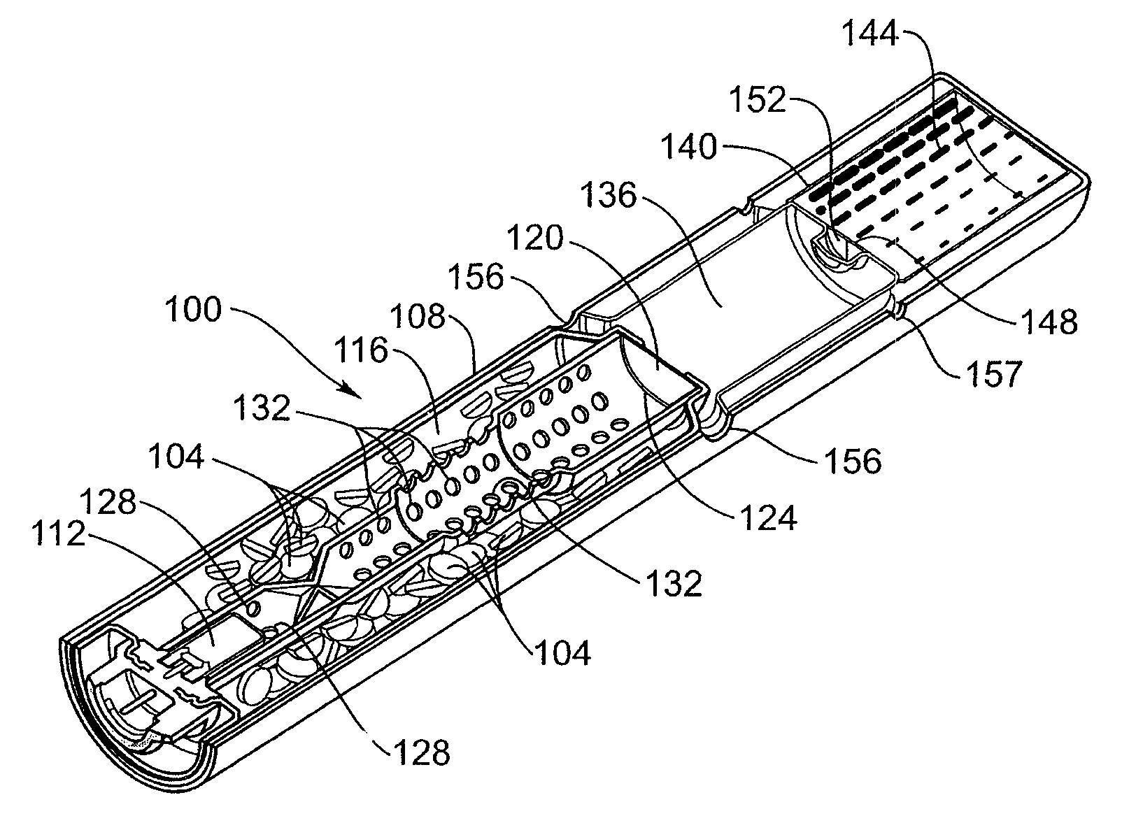
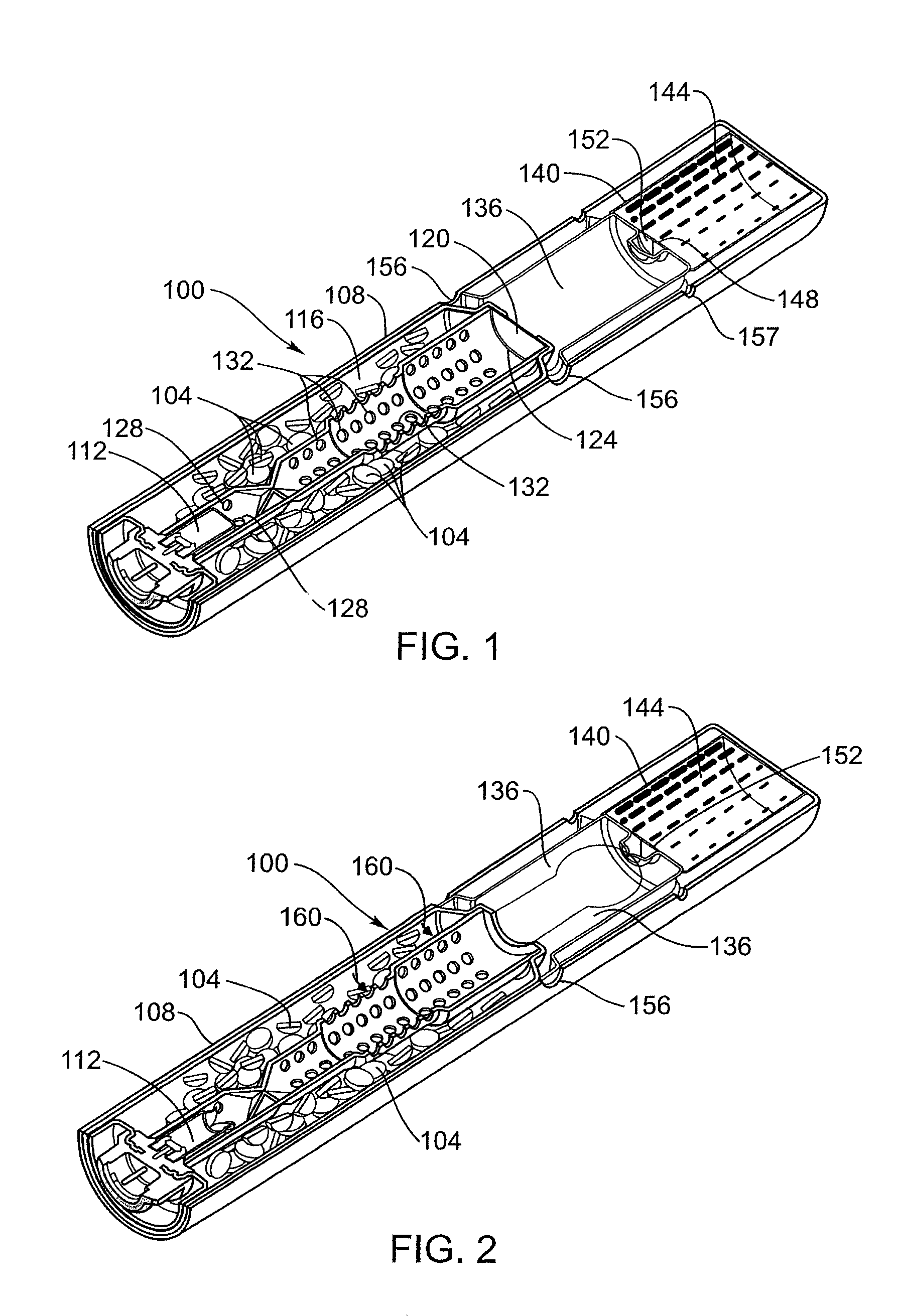
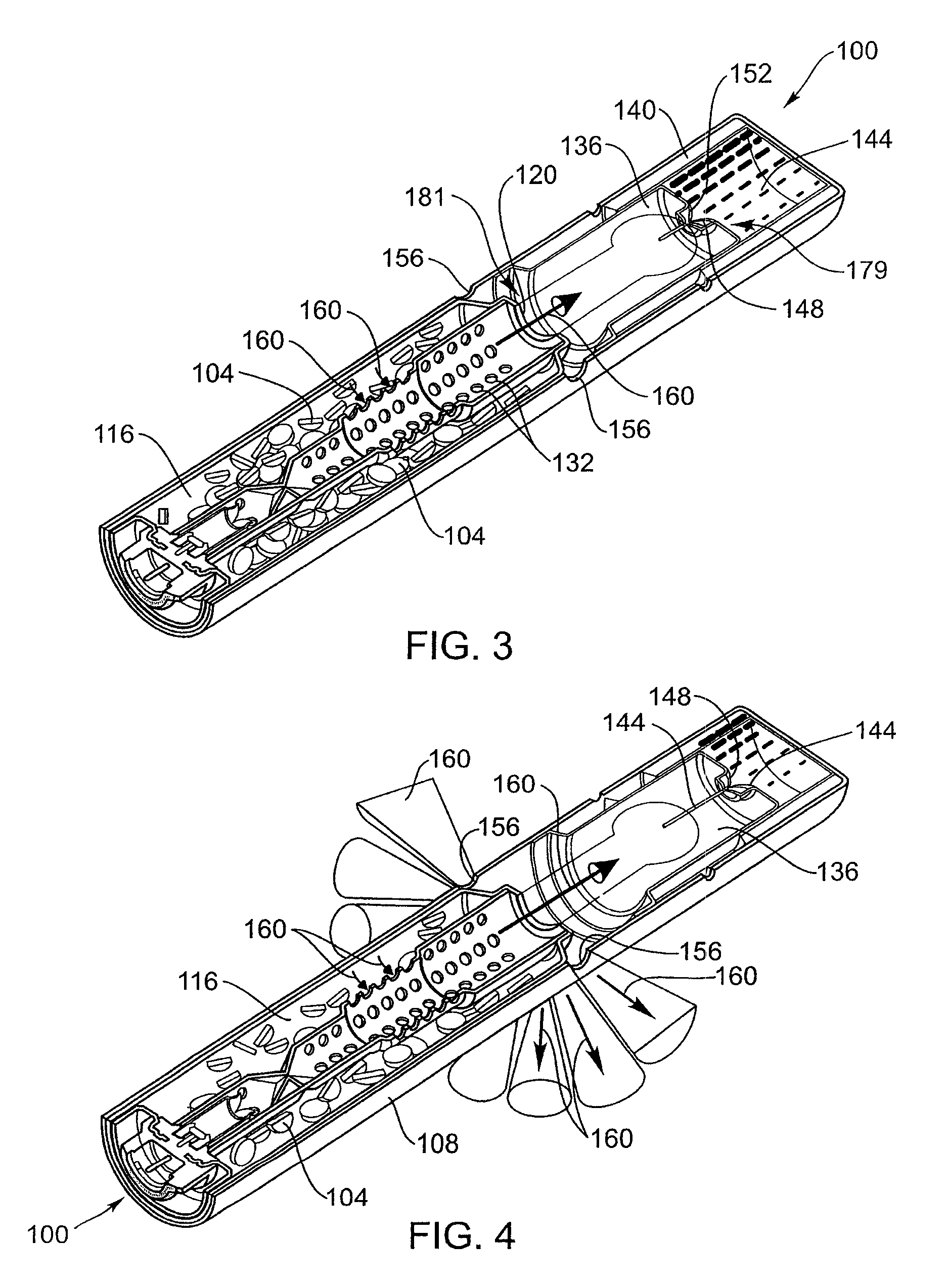
[0043]FIG. 1 illustrates an inflator device in accordance with a one embodiment of the invention and generally designated with the reference numeral 100. The inflator 100 includes a quantity of gas generant 104 contained within a housing 108. The inflator 100 also includes an initiator 112. The initiator 112 is used to ignite the gas generant 104. When the gas generant 104 is ignited, a quantity of inflation gas is formed. This gas may then be channeled into an airbag (not shown) to deploy the airbag. Those skilled in the art will appreciate that initiators and gas generants are known in the art and that a variety of different features may be used for these components.

[0044]The gas generant 104 is housed within a chamber 116 that is sealed by a burst disk 120. The chamber 116 is sometimes referred to as a “gas generant chamber.” ...


PUM


Abstract

An inflator that includes a quantity of gas generant housed within a chamber. A liquid including at least one of a fuel soluble in the liquid or an oxidizer soluble in the liquid and a piston are housed within another chamber of the inflator. This chamber is sealed. Upon actuation, movement of the piston hydraulically expels the liquid through an opening in the piston such that the liquid contacts the gas formed by combustion of the gas generant and cools the same. The fuel and/or oxidizer in the liquid can react to form additional gas.

Description

BACKGROUND OF THE INVENTION[0001]This invention relates generally to inflators for use in inflating inflatable restraint airbag cushions, such as used to provide impact protection to occupants of motor vehicles. More particularly, the invention relates to liquid-cooled inflators and the inclusion of performance enhancing additives therein.[0002]It is well known to protect a vehicle occupant by means of safety restraint systems which self-actuate from an undeployed to a deployed state without the need for intervention by the operator, i.e., “passive restraint systems.” Such systems commonly contain or include an inflatable vehicle occupant restraint or element, such as in the form of a cushion or bag, commonly referred to as an “airbag cushion.” In practice, such airbag cushions are typically designed to inflate or expand with gas when the vehicle encounters a sudden deceleration, such as in the event of a collision. Such airbag cushions may desirably deploy into one or more location...

Claims


Application Information

Patent Timeline
IPC IPC(8): B60R21/26
CPCB60R21/264B60R2021/26017B60R2021/2642
Inventor COX, MATTHEW A.SMITH, BRADLEY W.TAYLOR, ROBERT D.LUND, GARY K.JORDAN, MICHAEL P.
Owner AUTOLIV ASP INC
Why Eureka
Try Eureka