
LED illuminating device

a technology of led light and led module, which is applied in the direction of protective devices for lighting, lighting heating/cooling arrangements, decorative arts, etc., can solve the problems of high electrical consumption and overheating of the whole led package, short circuit of the circuit board or device failure, and high failure rate of the led package, so as to reduce the cost of freight and reduce the fault. , the effect of simple fram

Inactive Publication Date: 2011-02-15
WANG BAOLIANG
View PDF5 Cites 32 Cited by
  • Summary
  • Abstract
  • Description
  • Claims
  • Application Information

AI Technical Summary

Benefits of technology

This approach decreases manufacturing costs, minimizes the risk of short circuits, and enhances the operational efficiency and safety of LED devices by reducing wire length and complexity, while allowing for easier assembly and disassembly, and providing a more compact, energy-efficient, and versatile lighting solution.

Problems solved by technology

However, the drawbacks of the conventional LEDs are inflexibility, uncommonality and convenient limited.
Therefore when multiple colors are needed, many illuminating units should be aligned side by side in a complicated manner.
The complicated connection runs through the illuminating unit and the power source may result in high electrical consumption and overheating of the whole LED package.
Thus, it will cause a short circuit of the circuit board or device failure.
On the other hand, in recent years, the material cost of the copper has become more and more expensive.
The production of the LED illuminating device usually consumes lots of wire material.
Thus, it not only increase the manufacturing cost while producing the LED illuminating device, but also leads to a bulky appearance and difficult operation.

Method used


Image

  • LED illuminating device
  • LED illuminating device
  • LED illuminating device

Examples


third embodiment

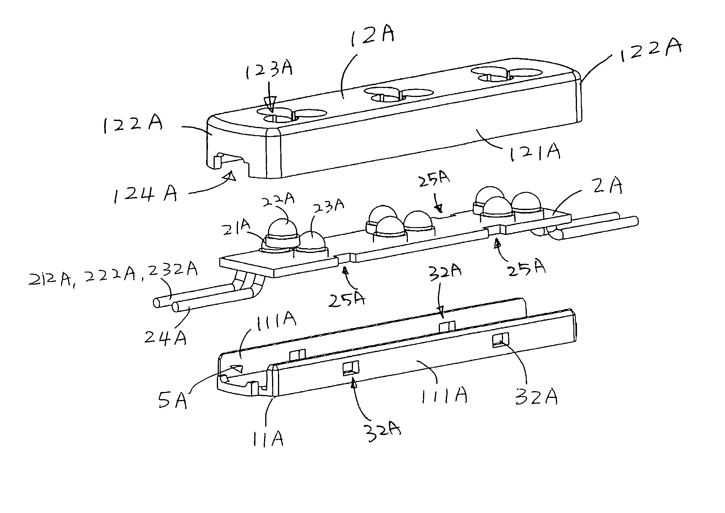
[0060]Referring to FIGS. 8 to 10 of the drawings, a LED illuminating arrangement according to the present invention is illustrated, wherein the LED illuminating arrangement comprises a plurality of LED illuminating devices connected with wires. Each of the LED illuminating devices comprises a shell 1A and an illuminating unit 4A.

[0061]The shell 1A, which is made of non-fragile materials such as plastic materials, comprises a supporting base 11A and a cover 12A engaging with the supporting base 11A to define a chamber 5A within the supporting base 11A and the cover 12A.

[0062]The illuminating unit 4A comprises a printed circuit board (PCB) 2A supported by the supporting base 11A of the shell 1A and having one or more LEDs 21A, 22A and 23A which are electrically and spacedly mounted on a PCB 2A disposed in the chamber 5A, wherein resin is filled to cover the LEDs 21A, 22A, 23A on the PCB 2A. There are three LED modules each comprises a red LED 21A, a green LED 22A, and a blue LED 23A c...

first embodiment

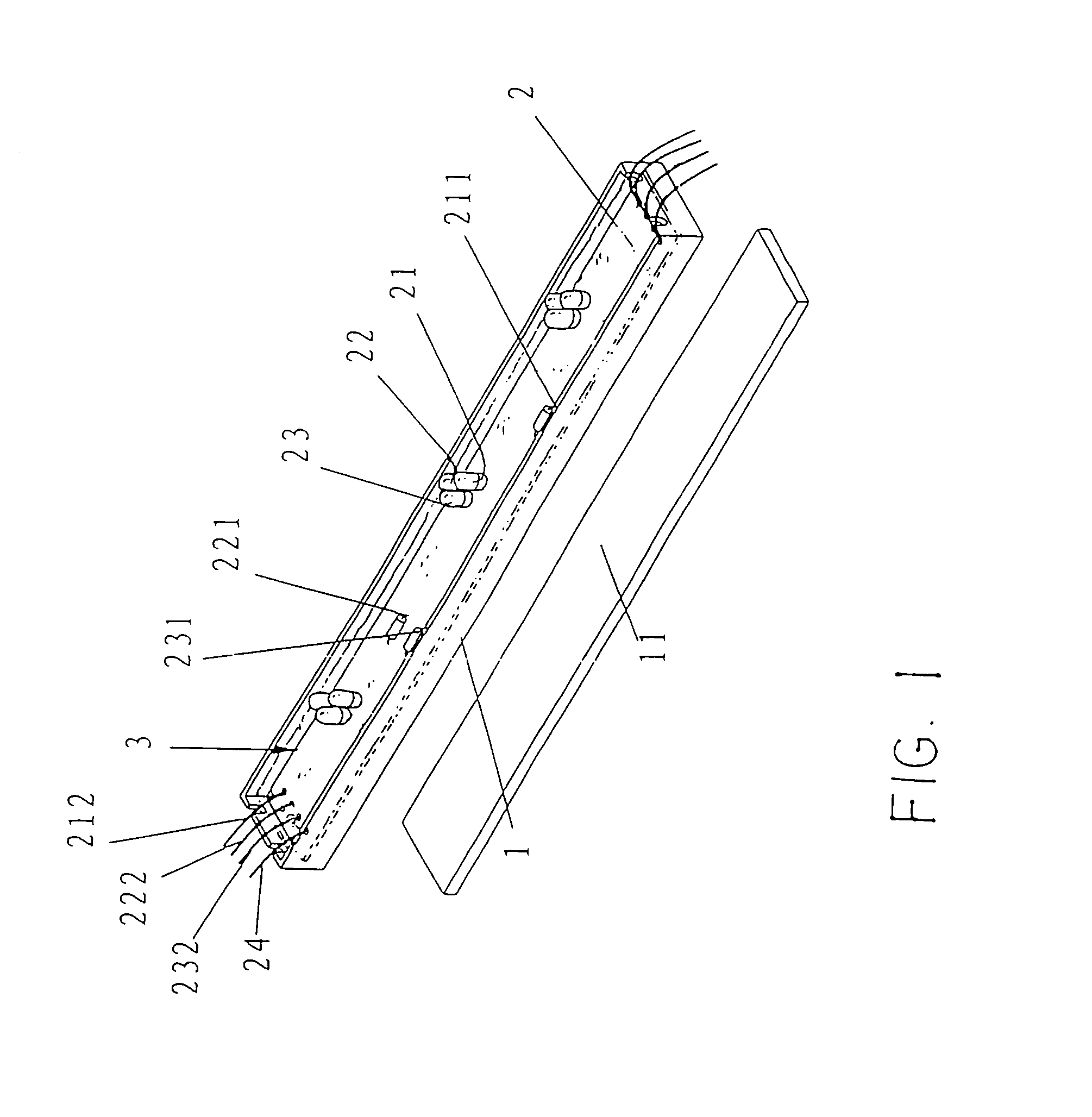
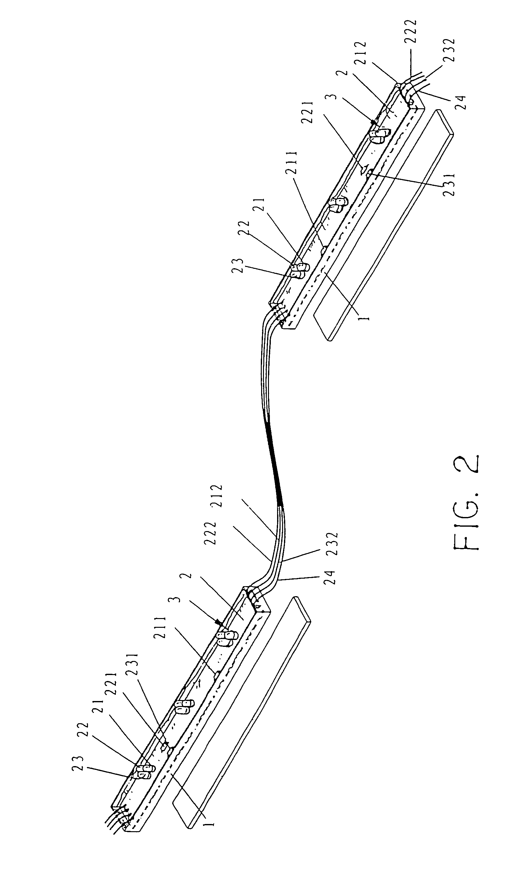
[0071]In the present invention, the required permanently angled wire increases the length of wire needed. According to the second preferred embodiment of the present invention, the blue, green, red wire, and the illuminating unit power lines are adapted to electrically link two neighboring LED modules with each other in a flat plane manner. In other words, through this method, the elimination of the permanent angle increases the efficiency of assembly because the wire doesn't need to bend. Finally, it reduces unnecessary length of the wire and minimizes the size of the device by decreasing the overall volume.

[0072]It is worth mentioning that a flat plane manner method to connect different LED modules eliminates the length of the connection wire and the power wire so as to save lots of material cost when producing. Moreover, such an easy, shorter connection between different modules also reduces the chance of shortcuts and errors. Most important of all, flat plane connection wires be...


PUM


Abstract

A LED illuminating device includes an illuminating unit and a shell having a top side and chamber. The illuminating unit includes a PCB supported by the shell and one or more LED modules electrically and spacedly mounted on the PCB disposed in the chamber. Each of the LED modules includes a red LED, a blue LED and a green LED which are symmetrically arranged in a triangular manner side by side. The wires are emerged from two ends of the shell in a horizontal plane parallel to an adhesive layer so as to adapt for electrically linking two neighboring LED modules with each other in a flat plane manner. Finally, it reduces unnecessary length of the wire and minimizes the size of the device by decreasing the overall volume.

Description

CROSS REFERENCE OF RELATED APPLICATION[0001]This is a CIP application of a non-provisional application having an application Ser. No. 11 / 583,470 and a filing date of Oct. 17, 2006 now abandoned.BACKGROUND OF THE PRESENT INVENTION[0002]1. Field of Invention[0003]The present invention relates ton illuminating device, and more particularly to a LED illuminating module[0004]2. Description of Related Arts[0005]The Light Emitting Diode (LED) is an excellent luminescence power providing many advantages such as lower power consumption and convenient for use. The LED is a fine cold source that can be a monocolor LED which has been widely utilized all over the world on lights and lanterns including traffic light while the chromatic LED, such as trichromatic LED, has been used in the large screen or electronic billboard for displaying figures or words. The arranged shape of LEDs is a rectangle or mounting different shape according to different pictorial circuit board (PCB board) on the billboa...

Claims


Application Information

Patent Timeline
Patent Type & Authority Patents(United States)
IPC IPC(8): F21V15/01
CPCF21S4/001F21V21/0808F21V31/04F21S4/003F21V21/08F21W2121/04F21Y2101/02F21Y2113/005F21S4/10F21S4/20F21Y2115/10F21Y2113/13F21V19/0035
Inventor WANG, BAOLIANG
Owner WANG BAOLIANG
Learn More