Bone screw retaining system

a technology of bone screw and retaining rod, which is applied in the field of osteosynthesis devices, can solve the problems of weak anchoring position and risk of assembly becoming unclamped, and achieve the effect of convenient fitting

Inactive Publication Date: 2011-02-15
STRYKER EURO OPERATIONS HLDG LLC
View PDF31 Cites 60 Cited by
  • Summary
  • Abstract
  • Description
  • Claims
  • Application Information

AI Technical Summary

Benefits of technology

[0007]One of the objects of the present invention is to provide a spinal implant which is easier to fit while at the same time being reliable.

Problems solved by technology

In such a system, the number of parts makes the clamping-in position of the anchoring members weak.
This leads to the risk of the assembly becoming unclamped, which is prejudicial to the patient.

Method used


Image

  • Bone screw retaining system
  • Bone screw retaining system
  • Bone screw retaining system

Examples


first embodiment

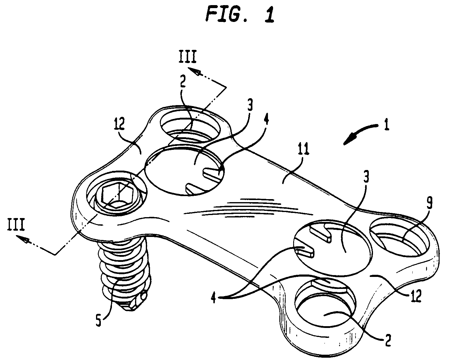
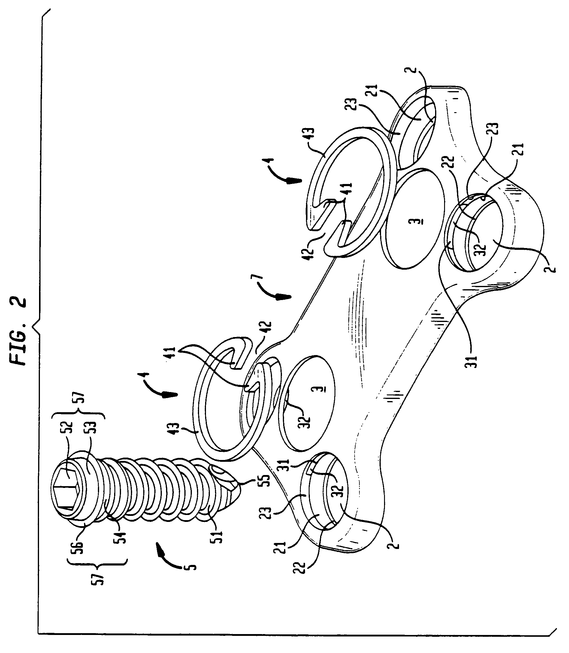
[0049]With reference to FIGS. 1 to 4c, there is shown the implant comprises a plate 1, bone screws 5 and circlips or split-rings 4. The plate 1 is a bone plate such as an anterior cervical plate or any other plate designed to be held on bone by bone screws. Plate 1 may join two bone parts or stabilize a fracture or may sit on a resected bone surface such as on a tibial plateau.

[0050]In the preferred embodiment, plate 1 is formed of a body 11 ending in two ends 12 which have a width slightly greater than that of a mid-zone of body 11. Each of the ends 12 comprises a pair of openings or orifices 2 which pass through the entire thickness of plate 1. The four openings are arranged geometrically as at four corners of a rectangle. Each of the openings 2 has a first, upper, cylindrical part 23 which continues in the form of a spherical central part 21 and ends in a second, lower, cylindrical part 22, the diameter of which is smaller than that of the first cylindrical part 23. The spherica...

second embodiment

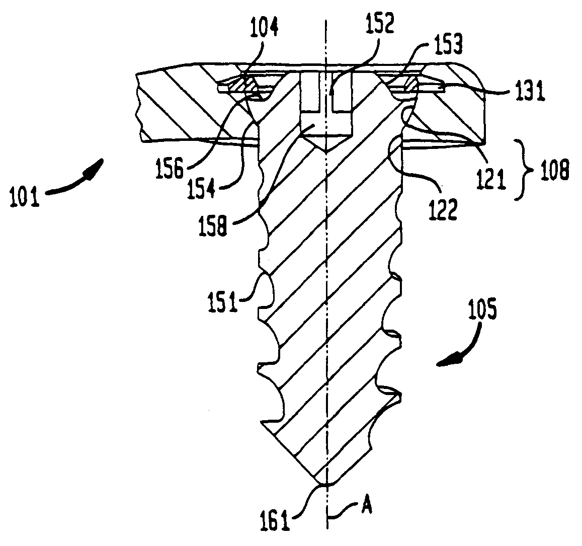
[0062]In a second embodiment illustrated by FIGS. 5 to 8c, cervical plate 1 is preferably still formed of a body 111 ending at two ends 112 which are slightly wider than the body 111. Each of the ends 112 still has a pair of openings 102 which pass right through the entire thickness of the plate 101. Each opening 102 has a first part 123 which is cylindrical, then a spherical intermediate part 121. Preferably, the orifice or opening 102 has a part 122 in the form of an angular cutout in the lengthwise direction of the plate 101. Preferably, the cutout allows the screw to pivot an angle B, preferably from 0° to 20°, in the lengthwise direction about axis 164, preferably the width of the cutout 122 is slightly less than its length. A circular recess or groove 131 is formed in the cylindrical part 123 of each opening 102. As in the previous embodiment, when used as an anterior cervical plate, the plate 101 has a curvature 13 in its longitudinal plane and a curvature 14 in its transvers...


PUM


Abstract

An implant, particularly for the spinal column, comprises a plate having openings, bone-anchoring members capable of being accommodated in the openings and at least one split-ring capable of holding the members in the orifices. The split-ring can come into direct contact with the anchoring member or members to hold the member or members in the orifices.

Description

CROSS-REFERENCE TO RELATED APPLICATIONS[0001]The present application is a continuation of U.S. Ser. No. 10 / 331,212 filed on Dec. 30, 2002 which is a divisional of U.S. Ser. No. 09 / 665,530 filed on Sep. 19, 2000, now U.S. Pat. No. 6,602,255.BACKGROUND OF THE INVENTION[0002]The present invention relates to osteosynthesis devices for the spinal column, the devices comprising a plate and a mechanism for locking a bone screw or anchoring member in position. This divisional application relates to tools used to remove a bone screw after it has been locked in the plate.[0003]U.S. Pat. No. 5,876,402 relates to an osteosynthesis plate comprising through-holes of conical shape capable of housing a bone screw with a completely spherical head to which is clipped, so as to form a ball-joint connection. A split coupling element of conical exterior shape complementing that of the hole is provided. A circlip reduces the aperture of the through-hole. A similar clip and groove arrangement is shown in ...

Claims


Application Information

Patent Timeline
Patent Type & Authority Patents(United States)
IPC IPC(8): A61B17/68A61B17/70A61B17/58A61B17/80A61B17/86A61B17/88A61B17/92A61F2/00A61F2/44
CPCA61B17/8042A61B17/88A61B17/8047A61B17/92A61B17/8875A61B17/7059A61B17/8635A61F2002/30497A61F2220/0025A61F2002/30495
Inventor CAMPBELL, CHRISTOPHER M.HARRINGTON, TODD
Owner STRYKER EURO OPERATIONS HLDG LLC
Why Eureka
Try Eureka