Intermittent operation circuit and modulation device
a technology of intermittent operation and modulation device, which is applied in the direction of generating/distributing signals, pulse techniques, instruments, etc., can solve the problems of limited frequency components of generated overshoot and undershoot, difficult ideal waveform shaping, and insufficient steep waveform of control signals, etc., to achieve rapid rise and fall and low power consumption
- Summary
- Abstract
- Description
- Claims
- Application Information
AI Technical Summary
Benefits of technology
Problems solved by technology
Method used
Image
Examples
embodiment 1
(1) Overall Configuration
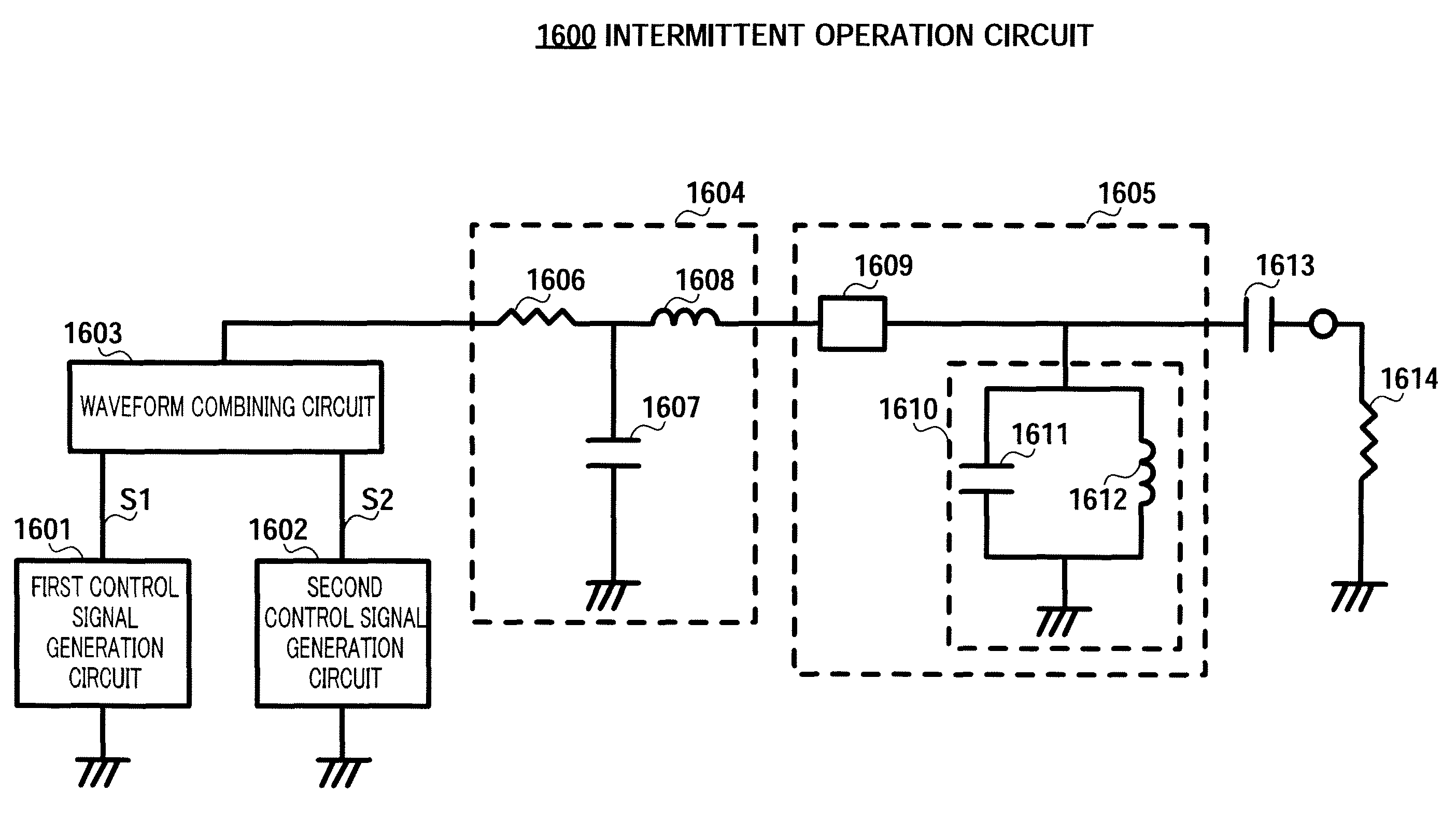
FIG. 5 shows the configuration of an intermittent operation circuit according to Embodiment 1 of the present invention. Intermittent operation circuit 100 has control signal generation circuits 101 and 102, a timing adjustment circuit 103, a waveform combining circuit 104, an impedance adjustment circuit 105, and an active circuit 106. Active circuit 106 is a circuit that includes a transistor or suchlike active element, such as an oscillator, for example.
Control signal generation circuit 101 generates a control signal S1, and control signal generation circuit 102 generates a control signal S2. The signal waveforms of S1 and S2 output by control signal generation circuits 101 and 102 are arbitrary, but will be assumed to be pulse waveforms in the following description.
Control signals S1 and S2 output from control signal generation circuits 101 and 102 are input to timing adjustment circuit 103 via terminals 110 and 111 respectively. Timing adjustment circuit...
embodiment 2
FIG. 24, in which parts corresponding to those in FIG. 5 are assigned the same reference codes as in FIG. 5, shows the configuration of a modulator according to this embodiment. Modulator 2000 has a transmit signal generation circuit 2001, a branching circuit 2002, and an intermittent operation circuit 100′ with virtually the same configuration as intermittent operation circuit 100 described in Embodiment 1. Intermittent operation circuit 100′ has a control signal generation circuit 2003 and control signal generation circuit 2004.
Transmit signal generation circuit 2001 generates a transmit signal S40, and transmits this to branching circuit 2002. Branching circuit 2002 inputs transmit signal S40 to both control signal generation circuits 2003 and 2004. In the case of this embodiment, an identical transmit signal S40 is input to control signal generation circuit 2003 and control signal generation circuit 2004.
Modulator 2000 is designed so that the waveforms of control signals S1 and ...
embodiment 3
FIG. 33 is a block diagram showing the configuration of a modulator of this embodiment. Modulator 2900 has a transmit signal generation circuit 2901, intermittent operation circuits 100′-1 and 100′-2 each configured in the same way as intermittent operation circuit 100′, an output switching circuit 2902, an inverter circuit 2903, and modulation circuits 2904-1 and 2904-2.
While ringing and stable oscillation frequencies and amplitude values are both the same in intermittent operation circuit 100′ output, in the case of intermittent operation circuit 100′-1 and intermittent operation circuit 100′-2 different circuit constants are set so that the amplitude values are the same but the frequencies differ.
In intermittent operation circuits 100′-1 and 100′-2, in the same way as shown in FIG. 24, output signals S62 and S64 from modulation circuits 2904-1 and 2904-2 (output signals from branching circuit 2002 in FIG. 24) are input to two control signal generation circuits.
FIG. 34 shows the n...
PUM
 Abstract
Description
Claims
Application Information
 - R&D
- Intellectual Property
- Life Sciences
- Materials
- Tech Scout
- Unparalleled Data Quality
- Higher Quality Content
- 60% Fewer Hallucinations
Browse by: Latest US Patents, China's latest patents, Technical Efficacy Thesaurus, Application Domain, Technology Topic, Popular Technical Reports.
© 2025 PatSnap. All rights reserved.Legal|Privacy policy|Modern Slavery Act Transparency Statement|Sitemap|About US| Contact US: help@patsnap.com


